EasyManua.ls Logo

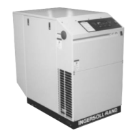
Ingersoll-Rand EPE 50 User Manual

Ingersoll-Rand EPE 50
62 pages
To Next Page IconTo Next Page
Page #1 background imageLoading...
Page #1 background image
XFE/EPE/HPE 50
XF/EP/HP 60
XF/EP/HP/XP 75-100
ML/MM/MH 37-75
OPERATORS/
INSTRUCTION MANUAL
OPTIONS
Before installation or starting the compressor for the
first time, this manual should be studied carefully to
obtain a clear knowledge of the unit and of the duties
to be performed while operating and maintaining the
unit.
RETAIN THIS MANUAL WITH UNIT.
This Technical manual contains IMPORTANT SAFETY
DATA and should be kept with the air compressor at all
times.
FORM: APDD 696C
July 2002
More Than Air. Answers.
Online answers: http://www.air.irco.com
Phone: 1-800-526-3615
CCN: 80440332 REV: C

Questions and Answers:

Ingersoll-Rand EPE 50 Specifications

General IconGeneral
BrandIngersoll-Rand
ModelEPE 50
CategoryAir Compressor
LanguageEnglish

Summary

0.0 SAFETY AND WARNINGS

0.1 SAFETY INSTRUCTIONS

Read all instructions carefully before installation and operation.

0.2 SAFETY PRECAUTIONS

Understand hazard signal words (DANGER, WARNING, CAUTION, NOTICE).

SAFETY SHUTDOWN

GENERAL WARNING

CRITICAL SAFETY WARNING

2.0 INSTALLATION

2.1 VENTILATION REQUIREMENTS

Ensure adequate ventilation for heat dissipation and prevent recirculation.

2.2 FOUNDATION REQUIREMENTS

Follow foundation plans for proper placement and vibration isolation.

2.3 PIPING GUIDELINES

Guidelines for air discharge piping, avoiding plastic and soldered copper.

2.4 ELECTRICAL INSTALLATION

ELECTRICAL INSTALLATION OVERVIEW

Confirm line voltage, starter box compliance, and electrical connections.

DRIVE MOTOR ROTATION CHECK

How to check and correct compressor drive motor rotation.

3.0 INTELLISYS CONTROLLER

INTELLISYS CONTROLLER OVERVIEW

Overview of the Intellisys controller display and its main functions.

3.1 EMERGENCY STOP SWITCH

Function of the emergency stop switch for immediate shutdown.

3.5 SET POINT PROCEDURE

3.6 WARNINGS

3.7 ALARMS

4.0 SYSTEMS

4.4 COMPRESSED AIR SYSTEM

4.5 COOLANT/AIR SEPARATION SYSTEM

4.6 ELECTRICAL SYSTEM

4.7 COMPRESSOR CONTROL SYSTEM

4.8 OPTIONS

5.0 SCHEDULED PREVENTATIVE MAINTENANCE

5.1 MAINTENANCE SCHEDULE

Specifies maintenance tasks and intervals based on hours or time.

5.4 INLET AIR FILTER

5.5 COOLANT FILTER

5.6 COOLANT

5.8 COOLANT SEPARATOR ELEMENT

5.10 MOTOR LUBRICATION

5.16 FLUID AND VIBRATION MONITORING

6.0 TROUBLE SHOOTING CHART

7.1 ELECTRICAL SCHEMATIC-FULL VOLTAGE

7.2 ELECTRICAL SCHEMATIC-STAR-DELTA

7.6 BASIC FLOW SCHEMATIC - AIR COOLED

7.7 BASIC FLOW SCHEMATIC - WATER COOLED

7.8 TYPICAL SYSTEM FLOW DIAGRAMS

8.0 WATER QUALITY RECOMMENDATIONS

Related product manuals