46
5.0 Membrane Switch
Background
The membrane switch is part of the user interface to the Intellisys control. It is a
matrix of switches bonded to the Intellisys controller and electrically connected to
the control circuit board. The internal membrane switch wiring to the physical
switches is accomplished through conducted traces made of silver conductive
ink. These electrical traces vary in length but will always measure less than 100
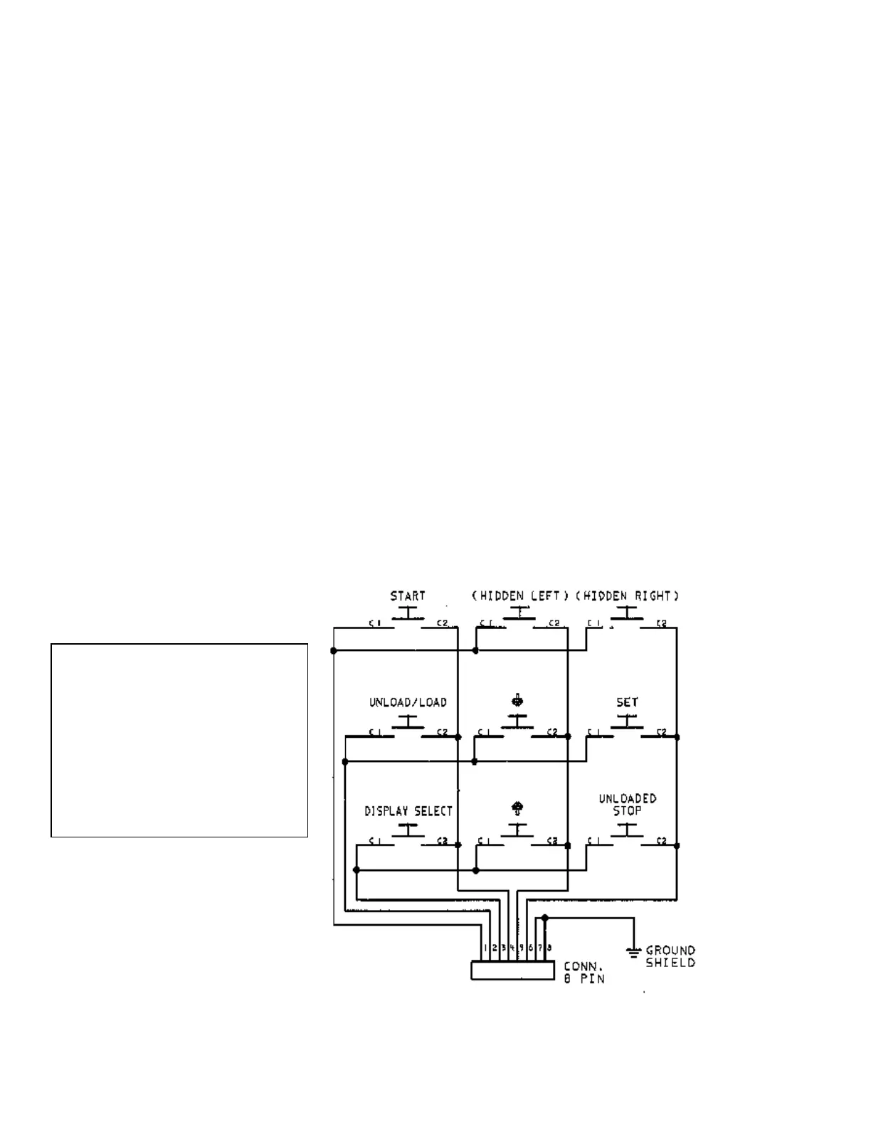
ohms when tested. The electrical schematic to Intellisys membrane switches is
shown in the diagrams below. The continuity of these switches can be tested
with the use of an ohmmeter. To test the individual switches use the following
procedure:
Procedure
1. Remove control power.
2. Disconnect the membrane switch tail connector from the controller.
3. Connect the ohmmeter to connector position that is wired to the switch (see
schematic below).
4. Verify ohmmeter reads O.L. (open circuit).
5. Press the membrane switch under test.
6. Verify ohmmeter reads less than 100 ohms.
Figure 1. SE Membrane Schematic
Start 1-4
Hidden Left 1-5
Hidden Right 1-6
Unload/Load 2-4
Down Arrow 2-5
Set 2-6
Display Select 3-4
Up Arrow 3-5
Unloaded Stop 3-6

 Loading...