

J
Jamie WilsonSep 14, 2025
What causes remote stop failure in Ingersoll-Rand Air Compressor?
What causes remote stop failure in Ingersoll-Rand Air Compressor?
| Model | R55 |
|---|---|
| Power | 55 kW |
| Horsepower | 75 hp |
| Power Source | Electric |
| Phase | 3 |
| Type | Rotary Screw |
| Max Pressure | 150 PSI |
| Pressure | 7.5 - 10 bar |
| Air Delivery | 243 CFM |
| Noise Level | 72 dB |
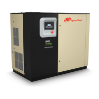
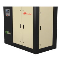
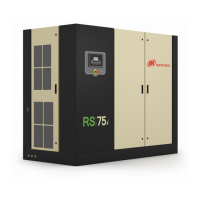
General overview of the compressor's features and specifications.
Important directive to retain operational guidelines for future reference.
Instructions for safely removing the compressor from its packaging.
Guidance for storing the compressor for extended periods.
Recommendations for selecting an appropriate installation site.
Guidelines for correctly installing air discharge and condensate drainage piping.
Electrical installation requirements and safety standards for the compressor.
Specific electrical requirements for VSD compressor installations.
Procedures for properly grounding the compressor system.
Methods to identify the electrical system configuration for proper connection.
Precautions and protection measures against high voltage events.
Information regarding the use of power factor compensation capacitors with VSDs.
Instructions for disconnecting EMC filters under specific electrical system conditions.
Considerations for power sources like transformers or generators.
Guidance on connecting the control power transformer.
Specifications and installation guidance for the cooling water piping.
Procedures for removing air from the water cooling system.
Instructions on how to completely drain the water cooling system.
Guidelines for maintaining optimal cooling water quality.
Procedure for adjusting the after-cooler trim valve for optimal performance.
Specific operational notes for fixed speed compressor models.
Explains the operation modes of the integrated dryer.
Fundamental steps for operating the compressor.
Pre-operational checks before starting the compressor.
The initial system check performed upon powering up.
The process of starting the compressor.
The procedure for safely stopping the compressor.
Operation mode for warming up the compressor's airend.
How the blower speed is managed for temperature control.
Procedure for immediate emergency shutdown of the compressor.
Steps to follow after an emergency stop.
Overview of the controller's display, buttons, and LEDs.
Explanation of the status indicators on the controller.
Functions of the primary command buttons on the controller.
How to use the keys for navigating the controller interface.
Description of the elements displayed on the controller screen.
How to navigate between different folders on the controller display.
Method for moving between pages within a folder.
How to view and adjust parameters within the controller.
Definitions of icons used on the system dashboard.
Explanations of messages displayed on the dashboard.
Settings specific to fixed speed compressor configurations.
The primary display screen showing system overview.
Detailed view and modification of operational parameters.
Display of real-time analog sensor readings.
Configuration options available to the operator.
Displays the current status of system filters.
Shows remaining service intervals and maintenance status.
Option to select the display language for the controller.
Security measure for accessing protected settings.
Settings specific to variable speed compressor configurations.
The primary display screen showing system overview.
Displays operational counters like power on and running hours.
Display of sensor readings and compressor operational data.
Configuration options available to the operator.
Displays the current status of system filters.
Shows remaining service intervals and maintenance status.
Option to select display language and units.
Security measure for accessing protected settings.
Displays the highest recorded values for various parameters.
Tools for troubleshooting Variable Speed Drive issues.
Parameters for setting up the compressor for optimal VSD operation.
Displays controller software version and details.
Overview of the controller's display, buttons, and LEDs.
Explanation of the status indicators on the controller.
Functions of the primary command buttons on the controller.
How to use the keys for navigating the controller interface.
Description of the elements displayed on the controller screen.
How to navigate between different folders on the controller display.
Method for moving between pages within a folder.
How to view and adjust parameters within the controller.
Definitions of icons used on the system dashboard.
Explanations of messages displayed on the dashboard.
The primary display screen showing system overview.
Displays operational counters like power on and running hours.
Access and adjustment of operator-configurable settings.
Displays the current status of system filters.
Shows remaining service intervals and maintenance status.
Option to select display language and units.
Configuration of network connectivity settings for ECO module.
Steps to enable communication and control from an X-Series system controller.
Security measure for accessing protected settings.
Displays the highest recorded values for various parameters.
Tools for troubleshooting Variable Speed Drive issues.
Parameters for setting up the compressor for optimal VSD operation.
Displays controller software version and details.
Physical connection and wiring for Modbus communication.
Considerations for RS-485 network installation and signal integrity.
Setting unique addresses for devices on the Modbus network.
Recommended configuration for the Modbus master device.
Assigning unique RS-485 addresses for X-Series network devices.
Steps to enable communication and control from an X-Series system controller.