Copyright Innovative Technology Ltd 2009 GA401-2
SMART HOPPER OPERATIONS MANUAL
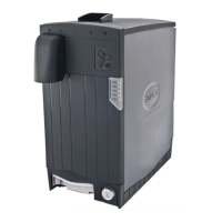
5.2.1 CONNECTION DIAGRAM
Figure 1 - SMART Hopper Connection Diagram
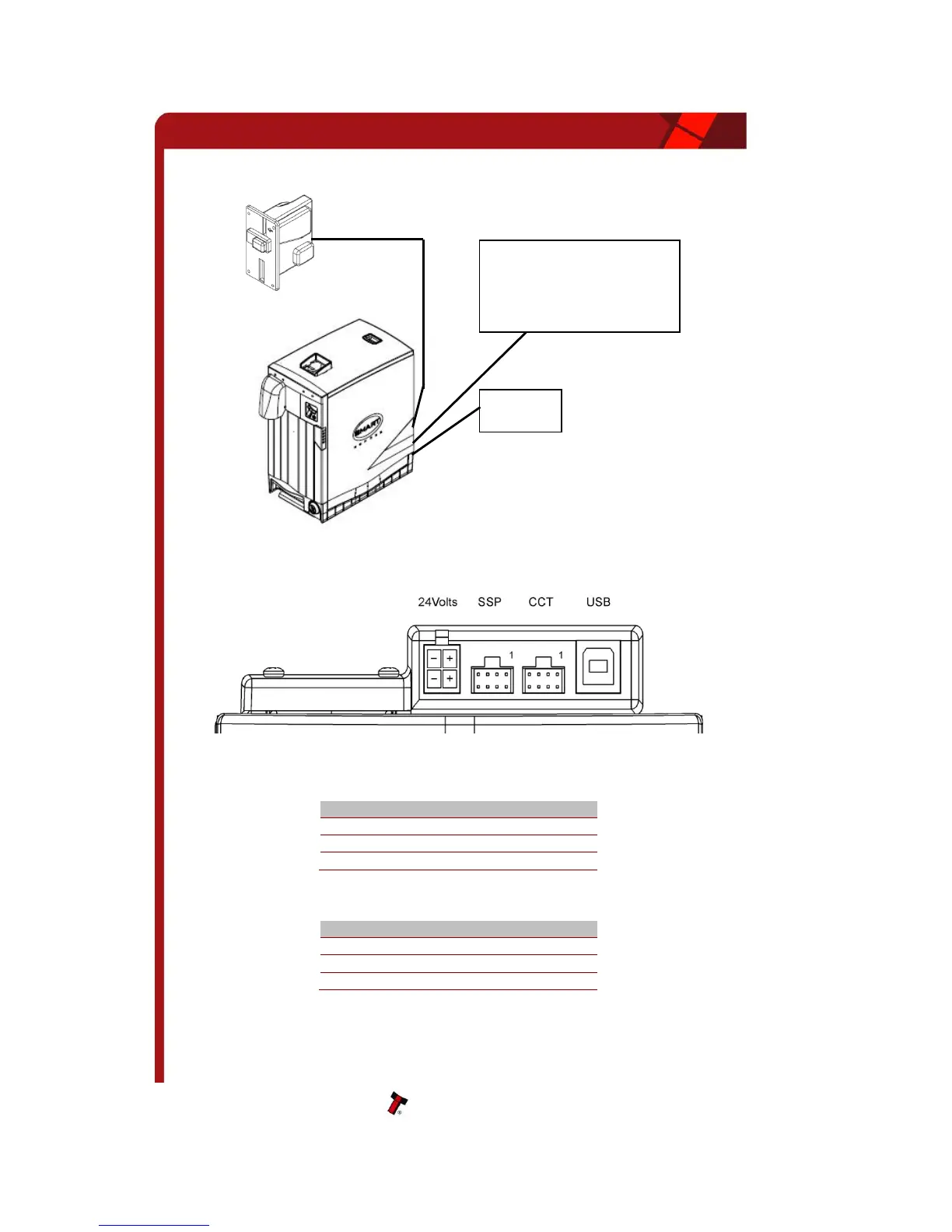
5.2.2 INTERFACE CONNECTOR
Figure 2 - Interface Connections location
eSSP Connections (Host Machine)
Table 8 – eSSP Host Connector Pin Details
CCT Connections (coin acceptor)
Table 9 - CCT Coin Acceptor Connections
The USB port can be used for eSSP communications in place of the eSSP Connector. Power
must be supplied via the 4-way 24 Volt connection
Host Machine
Control Board
WARNING
Always ensure that the bottom cash box
exit is clear to allow coins to exit the
hopper