Copyright Innovative Technology Ltd 2009 GA401-2
SMART HOPPER OPERATIONS MANUAL
4.2 LOCK INSTALLATION
The SMART Hopper has the option to add a lock that prevents the hopper being removed from the mounting plate. The hopper uses a standard lock PA650 which
includes all the parts shown with an asterisk *. The lock cam can be ordered from Innovative Technology, part MC211.
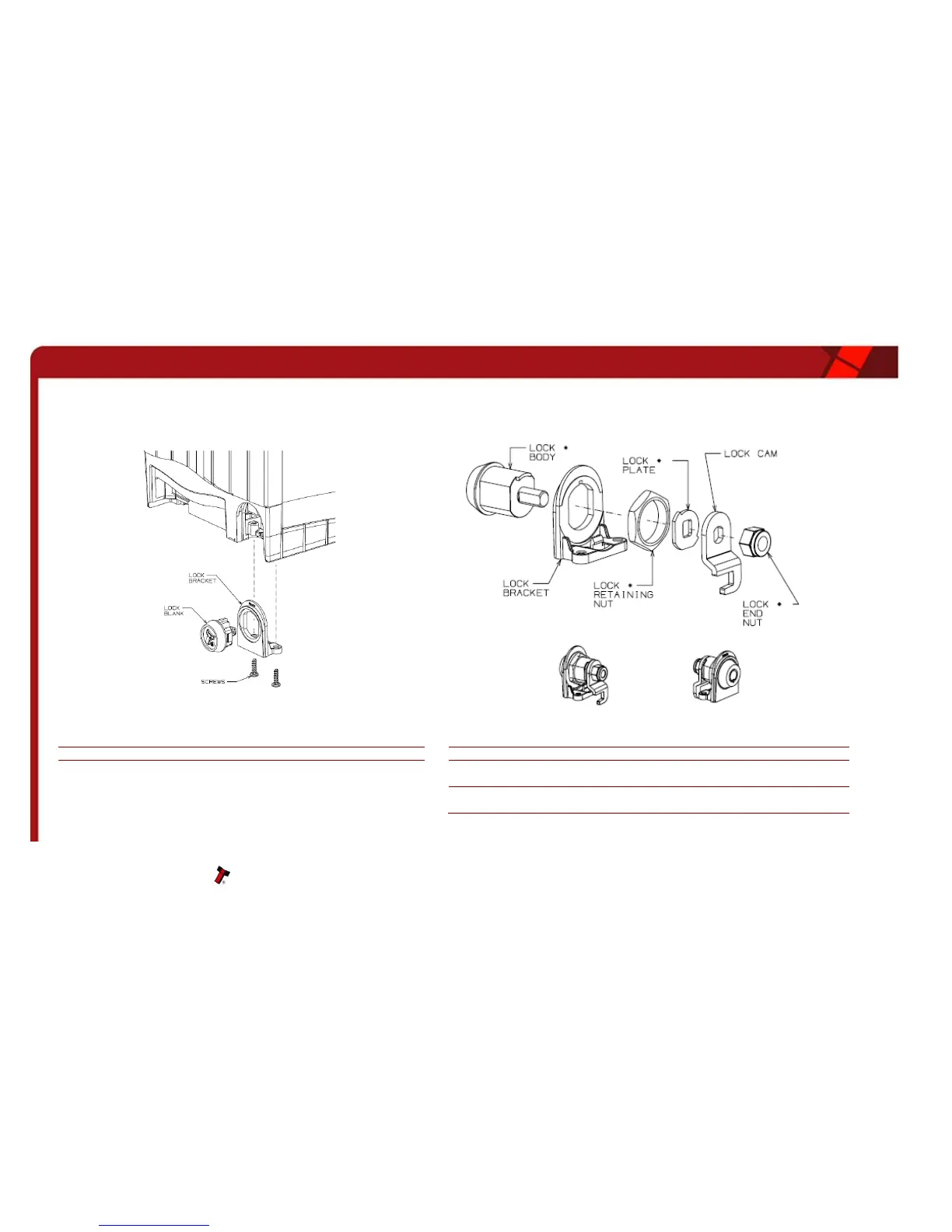
Remove the two screws from the base of the unit, and unclip the Lock
Bracket as shown
Assemble the lock in the order shown paying close attention to the orientation
of parts
Unclip the Lock Blank from the Lock Bracket
Place the Lock Bracket over the Lock Body and secure with the Retaining Nut
Place the Lock Plate and Lock Cam over the shaft of the Lock Body and secure
with the Lock End Nut
Fit the assembly to the base of the hopper unit and secure with the two screws.
(The Lock Blank is no longer required)