Version 1.4 Page 4
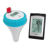
Figure2
3. Locatethedipswitchesontheinsidecoverofthelidofthetransmitter.
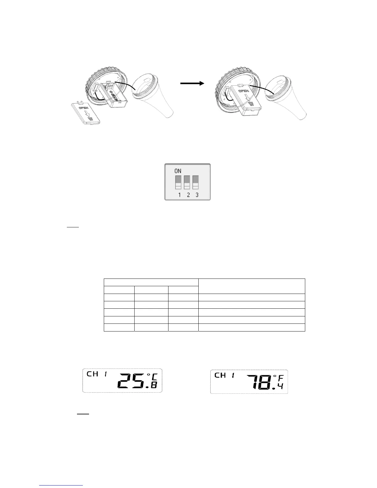
Figure3displaysallthreeswitchesintheOFFposition(down).
Figure3
Note:Thedefaultsettingis asfollow:DipSwitches1and2aredown,thistransmitterisasChannel1;
DipSwitch3isup,thetemperatureunitofthistransmitteris°C.
4. Channel Number: The display console supports up to 3 transmitters. To set each channel
number,changeDipSwitches1and2,asreferencedinTable1.
5. TemperatureUnitsofMeasure:Tochoosethetransmitterdisplay
unitsofmeasure(°F/°C),
changeDipSwitch3,asreferencedinTable1.
DIPSWITCH FUNCTION
1 2 3
DOWN DOWN‐‐‐ Channel1 (factorydefaultsetting)
UP DOWN‐‐‐ Channel2
DOWN UP‐‐‐Channel3
‐‐‐ ‐‐‐ DOWN
C (factorydefaultsetting)
Table1
6. Verifythecorrectchannelnumber(CH)andtemperatureunitsofmeasure(°F/° C ) areother
display,asshowninFigure4andFigure5.
Figure4Figure5
Note: The following illustration shows the full segments of the transmitter LCD for description
purposesonlyandwillnotappearlikethisduringnormaloperation.