■ Electric Specications
Item Name Rated Testing conditions Remarks
Insulation
resistor
Primary side-
SELV
≥2×10⁶Ω
Environment temperature: 25±5 °C.
Relative humidity:Lower than 90%
(non-condensing), testing voltage: 500 VDC
Based on your needs
Primary side- PE ≥2×10⁶Ω
Withstand
voltage
Reinforced
insulation
Primary side- SELV: 3250 VDC (or 2300 VAC ) or 1 minute
No discharge arc
or penetration, the
leakage current is
smaller than 10mA.
Basic insulation
Primary side- PE (or grounding casing):1900 VDC
(or 1350 VAC) for 1 minute
Pulse
Reinforced
insulation
Primary side- SELV: 4250 V pulse
No discharge arc or
penetration
Basic insulation Primary side- PE (or grounding casing):2500 V pulse
Range of rated
input voltage
AC input 100-240 VAC -
Rated input current Maximum 1.0 A -
IP level IP20 -
Pollution PD2 -
Elevation 2000 m ( 80 kPa) -
Over-voltage class Pluggable or xed devices powered from indoor sockets -
Highest working temperature 55 °C full load -
Over-current protection device Fuse -
4. Mechanical Design Reference
■ Installation Dimensions
50.0
90.0
ሿᗳ䀖⭥
Risk of electric shock
50.0
90.0
95.0
AM600
小心触电
Risk of electric shock
Figure 3 Installation dimensions (unit: mm)
5. Mechanical Design Reference
■ Selection of Cables
The following table shows the recommended power cables for reference:
Material Model
Cable diameter
Manufacturer Wire crimper
Chinese standard/MM
2
USA standard/AWG
Fork lug TNS2-4 1.0-2.0 17-14 Suzhou Yuanli
RYO-8
YYT-8
◆ The above lugs are applicable for power modules. The rated temperature is above 75 degrees Celsius. The
sectional area of the grounding cable should be larger than 2 mm².
■ Cable Processing
Cable processing steps:
1) Stripping the insulation layer. The exposed part should be 6 mm long;
2) Insert the cable into the cable pipe;
3) Penetrate the conductive part of the cable via the round hole of the lug. Use the recommended wire crimper
to crimp the cable;
4) Insert the cable into the 20 mm Φ3 heat-shrinkable tube. The part that covers the copper pipe of the lug will
shrink after being heated;
6m
Insert into the pipe
Use the wire crimper to crimp it
Figure 4 Cable processing
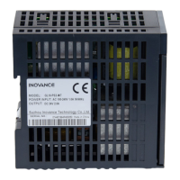
■ Terminal Signal Layout
L
N
100-240 VAC
INPUT
OUTPUT
24VDC-2A
POWER
Figure 5 Terminal signal layout
■ Terminal Denitions
Mark Type Function
L Input AC L input
N Input AC N input
Ground
Protective ground
(connecting to the AC input power ground cable)
Ground Functional ground (connecting to the PLC casing)
+24V Output 24 VDC positive
GND Output 24 VDC ground
■ Wiring Precautions
1) All external power supplies must be switched o before installation and wiring process to prevent electric
shock and module damage;
2) Thick cable (2 mm² at most) should be used as the 110V/220 VAC power cable. The cable should be twisted at
the connection terminal to connect the terminal at a smaller length. This can prevent short circuit caused by
loose screws;
3) Do not bundle the 110V/220 VAC power cables together with 24 VDC and IO signal cables and communication
cable. The distance between the cables should be as large as possible within the permitted range;
4) Only the copper cable of above 75℃ can be used. The screw fastening torque of the power terminal should be
9.5 kg-cm (8.25 in-lbs);
5) When the GL10 series module is used in a scenario with a strong interference source (such as AC drive), it is
recommended to use a noise lter to depress the interference noise. For details, please refer to the insulation
transformer;
6) After the power is switched on, if the 24 VDC indicator LED is ON, it means the power supply is working. If it is
OFF, the power input is exceptional and the module may be faulty.
■ Grounding
1) Terminal L and N of the AC power (100-240 VAC, 50/60 Hz) should be connected to the terminal L and N of
the power module. The grounding cable of the power supply must be connected to the terminal of the
module;
2) Terminal of the power module should be connected to the outer casing as the reference ground according
to the following grounding principles;
GL10-PS2
ަԆ䇮༷
অ⛩᧕ൠ˄ᴰ֣˅
ޡ᧕ൠ˄ݱ䇨˅
䘎᧕᧕ൠ˄нݱ䇨˅
GL10-PS2
ަԆ䇮༷
GL10-PS2
ަԆ䇮༷
᧕ൠ䝽㓯Ⲵ㓯ᖴнᗇሿҾ⭥ⓀㄟLǃNⲴ㓯ᖴ˗
ཊ⿽䇮༷ᰦ֯⭘ᰦˈ䈧࣑ᗵঅ⛩᧕ൠ˗
ᰐ⌅অ⛩᧕ൠⲴᛵߥлˈ䈧֯⭘മѝⲴޡ᧕ൠ˗
᧕ൠᰦˈн֯⭘മѝⲴ䘎᧕᧕ൠᯩᔿʽ
Other devices
Single-point grounding (best)
Other devices
Other devices
The diameter of the grounding cable must not be smaller than
the diameter of the power terminal L and N;
Use single-point grounding when multiple devices are used
concurrently;
When single-point grounding cannot be used, use common grounding
shown on the right side.
Do not use the grounding method shown on the right side.
Common grounding (permitted)
Connected grounding (not permitted)
Figure 6 Grounding requirements of the power module
5 64
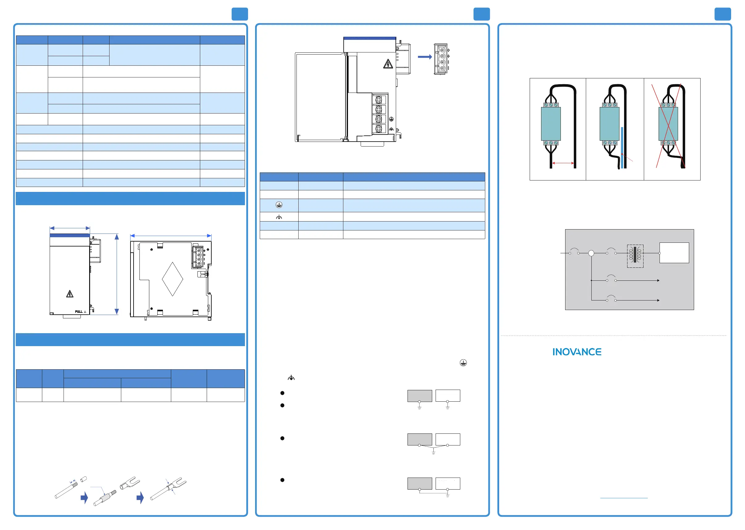
■ Mounting of the Power Filter
When the GL10 series module is used in a scenario with a strong interference source (such as AC drive), it is
recommended to use a noise lter to depress the interference noise.
The lter should be installed as close to the GL10 power module as possible. Use screws to x it on the conductive
back. The screw areas should be coated properly to ensure eective grounding. The incoming cable of the lter
should be laid separately from the outlet cable to prevent direct coupling of the noise of the incoming cable on the
outlet cable.
Output
Filter
Input
Not shielded
>20 cm
Output
Filter
Input
Output
Filter
Input
Shield
board
Correct wiring with a suitable distance
Correct wiring with a shielded board Wrong wiring
Figure 7 Mounting of the power lter
■ Insulation Transformer
The insulation transformer can reduce conducted noise (especially surge noise). Surge noise may cause false
tripping of the PLC. The insulation transformer should be connected as follows to reduce surge noise. The
insulation transformer can reduce the impact of thunder and lightning
PLC
Insulation
transformer
PLC
power
Trunk
terminal
block
Main
power
100Vac~240Vac
I/O equipment
Power
equipment
Cabinet
I/O power
Power supply
T1
Figure 8 Working principle of insulation transformer
Warranty Agreement
1) Inovance provides an 18-month free warranty to the equipment itself from the date of manufacturing for the
failure or damage under normal use conditions.
2) Within the warranty period, maintenance will be charged for the damage caused by the following reasons:
a. Improper use or repair/modication without prior permission
b. Fire, ood, abnormal voltage, natural disasters and secondary disasters
c. Hardware damage caused by dropping or transportation after procurement
d. Operations not following the user instructions
e. Damage out of the equipment (for example, external device factors)
3) The maintenance fee is charged according to the latest Maintenance Price List of Inovance.
4) If there is any problem during the service, contact Inovance's agent or Inovance directly.
5) Inovance reserves the rights for explanation of this agreement.
Suzhou Inovance Technology Co., Ltd.
Address: No.16, Youxiang Road, Yuexi Town, Wuzhong District, Suzhou 215104, P.R. China
Website:
h
t
t
p
:
/
/
w
w
w
.
i
n
o
v
a
n
c
e
.
c
o
m
 Loading...