Do you have a question about the Inovance GL20-4AD and is the answer not in the manual?
Document revision log including dates and versions.
Instructions on how to download the user guide PDF.
Details of the product's warranty period and conditions.
General safety guidelines for handling and operating the module.
Explanation of danger, warning, and caution indicators and their meanings.
Safety considerations for integrating the module into control systems.
Critical safety warnings related to module installation procedures and electrical knowledge.
Precautions for preventing electrical shock during installation and connection.
Essential safety warnings for wiring, emphasizing qualified personnel and proper insulation.
Safety advice on power supply stability and input voltage range for the product.
Safety measures for module maintenance, inspection, and handling.
Guidelines for environmentally responsible disposal of the product.
Technical details regarding the module's power supply requirements.
Detailed specifications for analog input voltage and current modes, resolution, and accuracy.
Specifications for software configuration, diagnostic reports, and parameter settings.
Diagram and dimensions for physically mounting the module onto a rail.
Procedures for installing modules side-by-side and onto a DIN rail.
Instructions on safely detaching the module from the DIN rail mounting.
Guidance on selecting appropriate cable lugs and diameters for connections.
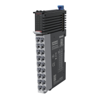
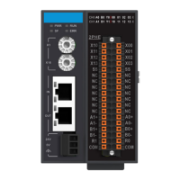
Defines the function and connection points of each terminal on the module.
Guidelines and precautions for wiring the module's terminals.
Schematic diagram illustrating voltage input wiring configurations.
Schematic diagram illustrating current input wiring configurations.
Step-by-step guide to adding the module in the development environment.
Configuring module channels, enabling access, and setting parameters in software.
Declaring ST variables for analog channels within the programming environment.
Mapping declared ST variables to specific module input channels.
Compiling, downloading, and executing the project on the PLC.
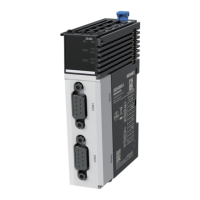
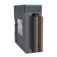
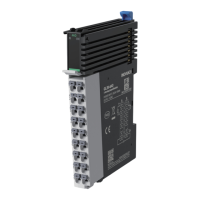
The GL20-4AD is a 4-channel analog input module designed for use with PLC masters, such as those in the Easy series. This module supports both voltage and current input with a 16-bit resolution, making it suitable for a variety of industrial applications requiring precise analog signal acquisition.
The primary function of the GL20-4AD module is to convert analog input signals (voltage or current) into digital data that can be processed by a programmable logic controller (PLC). It features four independent channels, allowing for simultaneous monitoring of multiple analog sensors or devices. The 16-bit resolution ensures high accuracy in the conversion process, capturing fine variations in the input signals.
The module is designed to integrate seamlessly into a control system, providing the necessary interface between analog field devices and the digital control logic of a PLC. It supports various voltage input ranges, including ±10 V, 0 to 10 V, ±5 V, 0 to 5 V, and 1 to 5 V, as well as current input ranges of ±20 mA, 0 to 20 mA, and 4 to 20 mA. This versatility allows it to accommodate a wide array of analog sensors and transducers commonly found in industrial environments.
The GL20-4AD module also incorporates several software-configurable features to enhance its functionality and adaptability. These include independent channel enable configuration, diagnostic report configuration, and diagnostic detection for short circuits and wire breaks (though wire break detection is only supported for 4 to 20 mA current input). Users can also configure the conversion mode and filter parameters, with a software filtering time range of 0 to 65535, allowing for noise reduction and signal conditioning. Overlimit detection and peak hold configuration are also supported, providing additional control and monitoring capabilities.
The module's digital output range is consistent with that of the GL10 series, defaulting to -20000 to 20000 and supporting up to ±32000. This provides flexibility in how the analog input values are represented digitally within the PLC system. The sampling time for all four channels is 250 µs, ensuring a relatively fast acquisition rate for dynamic processes. During stop mode, the module outputs the last sampled value and does not refresh, maintaining data integrity in specific operational states.
The GL20-4AD module is designed for straightforward mechanical and electrical installation. It can be installed side-by-side with other modules on a DIN rail, utilizing top and bottom guides for proper alignment. The DIN rail mounting hook automatically locks the module in place upon installation, and an end plate can be mounted on either side of the module assembly to secure it. Removal involves prying the DIN rail mounting hook upwards with a slotted screwdriver and pulling the module out.
For electrical connections, the module provides clearly defined terminals for each input channel, as well as power supply connections. Wiring precautions emphasize the importance of separating extension cables from power cables to prevent interference from noise, surge, and induction. The use of shielded cables is recommended to enhance interference resistance, and single-point grounding should be applied for shielded and solder-sealed cables.
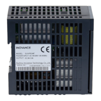
The module operates on a 24 VDC input power supply. It is crucial to ensure that the power input remains within the specified range of 24 VDC ±20% to prevent damage. Regular checks of the DC power stability provided by the switching-mode power supply unit are advised.
Programming the GL20-4AD involves adding the module to the PLC project, configuring its channels, and defining variables for the analog inputs. The channels can be configured for various voltage or current input ranges, and filter parameters can be adjusted to suit specific application requirements. This allows for fine-tuning the module's behavior to optimize performance for different types of analog signals.
Maintenance and inspection of the GL20-4AD module must be carried out by personnel with the necessary electrical training and experience. Several safety precautions are outlined to ensure safe operation and prevent damage to the equipment or personal injury. These include disconnecting all external power supplies before removing or installing the module, cleaning it, or re-tightening screws on the terminal block or connector. It is also critical not to touch the terminals while the power is on.
The module is designed for use in indoor electrical environments and must be installed in a control cabinet with a lock, providing a housing protection greater than IP20. This protects the module from dust, oil smoke, conductive dust, corrosive or combustible gases, high temperature, condensation, wind & rain, vibration, and impact, all of which could lead to electric shock, fire, malfunction, or product deterioration. Only authorized personnel with adequate electrical knowledge should open the cabinet.
In terms of diagnostic capabilities, the module supports diagnostic report configuration and detection for short circuits and wire breaks (for 4-20mA current input). These features aid in troubleshooting and identifying potential issues within the analog input system, facilitating quicker maintenance and minimizing downtime.
For disposal, scrapped products should be treated as industrial waste, and batteries should be disposed of according to local laws and regulations. Recycling retired equipment in accordance with industry disposal standards is encouraged to prevent environmental pollution. The warranty period for the product is 18 months from the date of manufacture, with a maintenance fee charged for damages caused by operations not following user instructions, force majeure events, or use outside the intended scope.
| Type | Analog Input Module |
|---|---|
| Number of Analog Inputs | 4 |
| Number of Channels | 4 |
| Input Type | Voltage/Current |
| Current Input Range | 0-20mA, 4-20mA |
| Resolution | 16-bit |
| Protection Class | IP20 |
| Certifications | CE, RoHS |
| Accuracy | ±0.1% F.S. |
| Operating Voltage | 24VDC ±10% |
| Storage Temperature | +70°C |
| Relative Humidity | 5% to 95% (non-condensing) |