Do you have a question about the Inovance IMC30-6G Series and is the answer not in the manual?
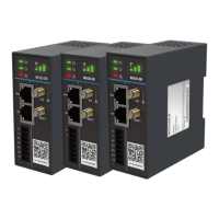
Identifies product nameplate details and model variations.
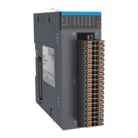
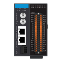
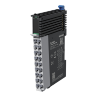
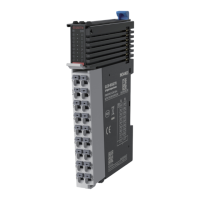
Lists and describes the physical components of the axis control module.
Provides detailed physical dimensions and measurements of the module.
Details electrical and performance specifications for the module's functions.
Outlines the available product models and their corresponding features.
Details the high-speed position comparison output interface and its wiring connections.
Explains the PWM output interface, including signal definitions and wiring.
Provides essential information on the pulse control output interface and its wiring.
Details the general input interface, pin definitions, and wiring requirements.
Covers the power interface, including power input and ground connections.
Introduces different control modes and their wiring configurations.
Illustrates the wiring for servo control mode connections.
Shows the wiring methods for stepper control modes.
Specifies the power supply requirements for the IMC30-6G module.
Illustrates the power supply connection diagram for the module.
| Model | IMC30-6G Series |
|---|---|
| Category | Control Unit |
| Protection Level | IP20 |
| Humidity | 5% to 95% RH, non-condensing |
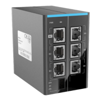
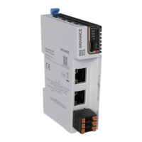
| Communication Interface | CAN |
| Storage Temperature | -20°C to 60°C |