Do you have a question about the Inovance GR10-2PHE and is the answer not in the manual?
General safety advice and warnings for installation, use, and maintenance.
Explains WARNING, CAUTION, and DANGER labels for safety guidance.
Safety considerations for designing control systems for the module.
Safety measures during the installation of the module.
Safety precautions and guidelines for wiring the module.
Safety guidelines for operating and maintaining the module.
Proper procedures for disposing of the module as industrial waste.
Details the module's model number, nameplate, and related information.
Lists the overall technical specifications of the module.
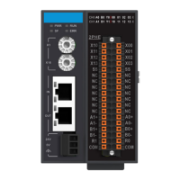
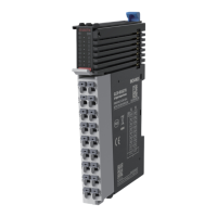
Describes the physical external interface and port layout.
Details the specific electrical output characteristics of the module.
Details the specific electrical input characteristics of the module.
The Inovance GR10-2PHE HS Differential Pulse Positioning Module is a specialized device designed for high-speed, precise motion control applications. This module offers two channels of 4 MHz high-speed differential outputs, making it suitable for systems requiring accurate and rapid positioning.
The primary function of the GR10-2PHE module is to generate high-speed differential pulse outputs for controlling various motion systems, such as servo drives or stepper motors. It supports multiple pulse output modes, including "direction + pulse" and "CW/CCW" (clockwise/counter-clockwise), providing flexibility for different motor control strategies. This allows for precise control over motor speed, direction, and position.
Beyond basic pulse generation, the module also incorporates advanced positioning features. It supports homing positioning, which is crucial for establishing a known reference point for motion systems. Additionally, it includes left and right limiting functions, enabling the definition of operational boundaries to prevent over-travel and ensure safe operation of the connected machinery. These features make it an ideal choice for applications that demand a large number of axes and high precision.
The GR10-2PHE module integrates seamlessly into EtherCAT industrial real-time bus systems, leveraging its 100 Mbps communication speed for efficient data exchange. This allows for synchronized control of multiple modules and axes within a larger automation system, ensuring coordinated and precise movements. The EtherCAT protocol supports various services, including COE (PDO, SDO), facilitating robust and flexible communication with other EtherCAT devices.
The GR10-2PHE module is designed for ease of integration and reliable operation within industrial control environments. It features a clear model number and nameplate, providing essential information such as the model name (GR10-2PHE), rated input (24VDC 250mA), rated output (5VDC 150mA DIFF LOAD), version number, and serial number. This helps in identification and tracking of the module.
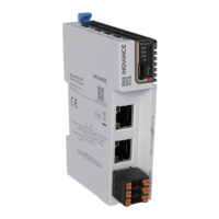
The module's external interface includes several indicators and ports for monitoring and connectivity. State indicators for Power (PWR), Run (RUN), System Fault (SF), and Error (ERR) provide visual feedback on the module's operational status. Green LEDs indicate normal operation (power on, running normally, channel ready to output, input signal active), while red LEDs signal faults or errors, aiding in quick troubleshooting.
For configuration, the module incorporates a 16-bit station address rotary switch, allowing users to set the decimal slave address from 0 to 255. This is essential for assigning unique addresses to each module within an EtherCAT network.
Communication is handled via dedicated EtherCAT input (X1 IN) and output (X2 OUT) ports, which facilitate connection to other EtherCAT slaves in a daisy-chain or linear topology. This design simplifies network wiring and expansion.
The module also includes 24V power input terminals and user output terminals, which are detailed in the "Electrical Design Reference" section of the manual. These terminals are designed for secure and reliable electrical connections.
The GR10-2PHE supports both sink and source input types for its digital inputs, offering flexibility for various sensor and control signal configurations. The differential pulse outputs are designed for high-frequency operation (up to 4 MHz) and support multiple output modes, including pulse+direction, A/B phase single frequency, and CW/CCW, catering to a wide range of motor control requirements.
Maintenance and inspection of the GR10-2PHE module are critical for ensuring its long-term reliability and safe operation. The design emphasizes clear visual indicators and straightforward procedures to facilitate maintenance tasks.
The state indicators (PWR, RUN, SF, ERR) provide immediate feedback on the module's health, allowing maintenance personnel to quickly identify operational issues. A green RUN indicator confirms normal operation, while a red SF or ERR indicator signals a fault or state machine error, prompting investigation.
For wiring, the module's terminal blocks are designed for secure connections. The manual provides guidance on proper tightening torque to prevent issues like short-circuits or poor contact. The use of shielded cables for high-frequency signals is recommended in environments with serious interference to enhance anti-interference ability, contributing to system stability and reducing maintenance needs related to signal integrity.
The module's open-type design, intended for installation within a control cabinet with IP20 protection, ensures that it is shielded from dust, oil smoke, conductive dust, corrosive or combustible gases, and adverse environmental conditions. This protective enclosure minimizes the risk of damage or deterioration, thereby reducing the frequency of maintenance.
Firmware upgrades can be performed via a USB port, allowing for easy updates and bug fixes without requiring complex procedures. This feature ensures that the module can be kept up-to-date with the latest software enhancements and security patches.
In terms of physical maintenance, the manual advises against touching terminals while power is on and emphasizes disconnecting all external power supplies before cleaning the module or re-tightening screws. This ensures the safety of maintenance personnel and prevents electrical shock or damage to the equipment. Similarly, all external power supplies must be disconnected before removing the module or connecting/removing communication wirings.
The module's design also considers the prevention of foreign matter ingress. A label on the top of the module prevents debris from entering during wiring, which should be removed before system operation to facilitate ventilation.
For disposal, the module is treated as industrial waste, and its battery should be disposed of according to local laws and regulations, promoting environmental responsibility.
Overall, the Inovance GR10-2PHE module is engineered for high-performance motion control, offering robust features for precise positioning, reliable communication, and user-friendly maintenance, making it a valuable component in advanced automation systems.
| Category | Control Unit |
|---|---|
| Input Voltage | 24 VDC |
| Storage Temperature | -20°C to +70°C |
| Weight | 150g |
| Product name | GR10-2PHE |
| Output Current | 2A |
| Protection | Overcurrent |
| Operating Temperature | +55°C |
| Humidity | 5% to 95% (non-condensing) |