Inovance H0U Series PLC User Manual
Page 8 of 14
the terminal is ON and is inactive (state "0") when the terminal is OFF.
The 250 VAC reinforced insulation must be satisfied between the relay outputs and the
logic circuit of the PLC. In addition, the 250 VAC reinforced insulation must be satisfied
between the output terminals of different common terminals.
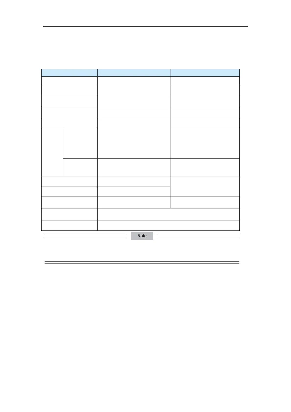
Item Relay Output Transistor Output
Circuit voltage 250 VAC, 30 VDC below 5–24 VDC
Circuit insulation Relay mechanical insulation Optically coupling insulation
Action indication Output contact closing
Contact closing when optically
coupling is driven
Leakage current at open
circuit
- < 0.1 mA/30 VDC
Minimum load 2 mA/5 VDC 5 mA (5–24 VDC)
Resistive load
2 A for a point
8 A for 4 points in a group sharing
a common terminal
8 A for 8 points in a group sharing
a common terminal
0.5 A for a point
0.8 A for 4 points
1.6 A for 8 points
Maximu
m
output
current
Inductive load 220 VAC, 80 VA
High-speed outputs: 7.2 W/24
VDC
Others: 12 W/24 VDC
ON response time 20 ms (max.)
OFF response time 20 ms (max.)
High-speed outputs: 10 us
Others: 0.5 ms
High-speed output
frequency
-
100 kHz per channel (max.)
Output common terminal
Each group shares a common terminal COM. The groups are
insulated.
Fuse protection -
When some or all transistors in each group are with load, the average current for each channel must not
exceed 0.2 A. The maximum current for a single channel must not exceed 0.5 A.
Internal Equivalent Circuit
The following figure shows the internal equivalent circuit of relay output. Output terminals
are divided into several groups, with each group electrically isolated. The output contacts
of different groups are connected to different power circuits.
efesotomas
on.com

 Loading...


