EasyManuals Logo

Inovance H0U Series User Manual

Inovance H0U Series
14 pages
To Next Page IconTo Next Page
To Previous Page IconTo Previous Page
Page #9 background imageLoading...
Page #9 background image
Inovance H0U Series PLC User Manual
Page 9 of 14
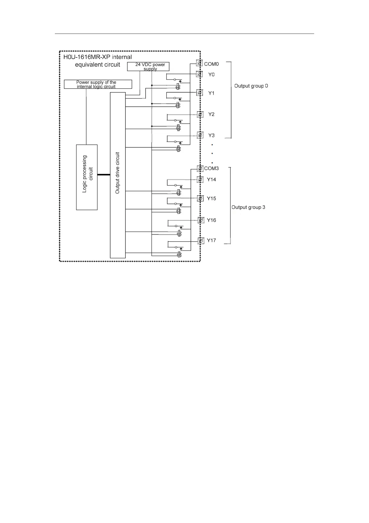
The following figure shows the internal equivalent circuit of mixed output of transistor and
relay. Output terminals are divided into several groups, with each group electrically
isolated. The output contacts of different groups are connected to different power circuits.
Transistor output can be applied only to 24 VDC load circuit.
efesotomas
y
on.com

Other manuals for Inovance H0U Series

Questions and Answers:

Question and Answer IconNeed help?

Do you have a question about the Inovance H0U Series and is the answer not in the manual?

Inovance H0U Series Specifications

General IconGeneral
BrandInovance
ModelH0U Series
CategoryController
LanguageEnglish

Related product manuals