Description of Function Codes
MD380 User Manual
- 156 -
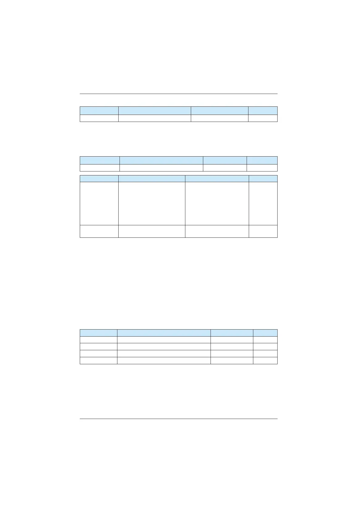
Function Code Parameter Name Setting Range Default
F2-06 Vector control slip gain 50%–200% 100%
)RU6)9&LWLVXVHGWRDGMXVWVSHHGVWDELOLW\DFFXUDF\RIWKHPRWRU:KHQWKHPRWRUZLWK
load runs at a very low speed, increase the value of this parameter; when the motor with
load runs at a very large speed, decrease the value of this parameter.
For CLVC, it is used to adjust the output current of the AC drive with same load.
Function Code Parameter Name Setting Range Default
F2-07 69&WRUTXH¿OWHUWLPHFRQVWDQW 1–31 28
Function Code Parameter Name Setting Range Default
F2-09
Torque upper limit source in
speed control mode
0: F2-10
1: AI1
2: AI2
3: AI3
4: Pulse reference (DI5)
5: Communication reference
0
F2-10
Digital setting of torque upper
limit in speed control mode
0.0%–200.0% 150.0%
In the speed control mode, the maximum output torque of the AC drive is restricted by F2-
09. If the torque upper limit is analog, pulse or communication setting, 100% of the setting
corresponds to the value of F2-10, and 100% of the value of F2-10 corresponds to the AC
drive rated torque.
For details on the AI1, AI2 and AI3 setting, see the description of the AI curves in group F4.
For details on the pulse setting, see the description of F4-28 to F4-32.
:KHQWKH$&GULYHLVLQFRPPXQLFDWLRQZLWKWKHPDVWHULI)LVVHWWR³FRPPXQLFDWLRQ
VHWWLQJ´)³'LJLWDOVHWWLQJRIWRUTXHXSSHUOLPLWLQVSHHGFRQWUROPRGH´FDQEHVHWYLD
communication from the master.
In other conditions, the host computer writes data -100.00% to 100.00% by the
communication address 0x1000, where 100.0% corresponds to the value of F2-10. The
FRPPXQLFDWLRQSURWRFROFDQEH0RGEXV&$1RSHQ&$1OLQNRU352),%86'3
Function Code Parameter Name Setting Range Default
F2-13 Excitation adjustment proportional gain 0–20000 2000
F2-14 Excitation adjustment integral gain 0–20000 1300
F2-15 Torque adjustment proportional gain 0–20000 2000
F2-16 Torque adjustment integral gain 0–20000 1300
These are current loop PI parameters for vector control. These parameters are automatically
REWDLQHGWKURXJK$V\QFKURQRXVPRWRUFRPSOHWHDXWRWXQLQJDQGQHHGQRWEHPRGL¿HG
The dimension of the current loop integral regulator is integral gain rather than integral time.
Note that too large current loop PI gain may lead to oscillation of the entire control loop.
Therefore, when current oscillation or torque fluctuation is great, manually decrease the
proportional gain or integral gain here.
efesotomasyon.com
 Loading...
