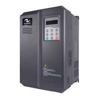
MD380 User Manual Mechanical and Electrical Installation
- 41 -
(OHFWULFDO:LULQJRIWKH0'
)LJXUH(OHFWULFDO:LULQJRIWKH0'VLQJOHSKDVH9
DI1
DI2
DI3
DI4
DI5
&20
L1
L2
W
V
U
–
+
PB
+24V
23
T/C
T/B
T/A
250 VAC 10 mA to 3 A
30 VDC 10 mA to 1 A
+10V
AI1
AI2
GND
PE
1
2
3
+10 V 10 mA
0
–1
0 VDC
0
–1
0 VDC/4
–
20 mA
1–5 kȍ
J8
I
V
VI
J5
&20
FM
GND
'21
CME
$21
0
–
10 V/0
–
20 mA
J12
J3
J7
0
–
24 V/0
–
50 mA
MCCB
23
J4
J13
&20
Single-phase 220 V
50/60 Hz
Braking resistor
Digital input 1
Digital input 2
Digital input 3
Digital input 4
High-speed
pulse input
MD380
Fault contact output
Power for
setting frequency
Analog input 1
Analog input 2
Analog output
External operation panel interface
PG card interface
Extension card interface
2SHQ-collector output
2SHQ-collector 1
2SHQ-collector 2
(High-speed
pulse output)
M
Connect to
the housing
Note
The control circuit wiring of all MD380 modelsare similar.
Ƽ Indicates the main circuit terminal, and ƻ indicates the control circuit terminal.
efesotomasyon.com

 Loading...


