MD380 User Manual Mechanical and Electrical Installation
- 43 -
:LULQJRI',WHUPLQDOV
*HQHUDOO\XVHWKHVKLHOGHGFDEOHQRWORQJHUWKDQP:KHQDFWLYHGULYLQJLVDGRSWHG
QHFHVVDU\¿OWHULQJPHDVXUHVVKDOOEHWDNHQWRSUHYHQWWKHLQWHUIHUHQFHWRWKHSRZHU
supply. The contact control mode is recommended.
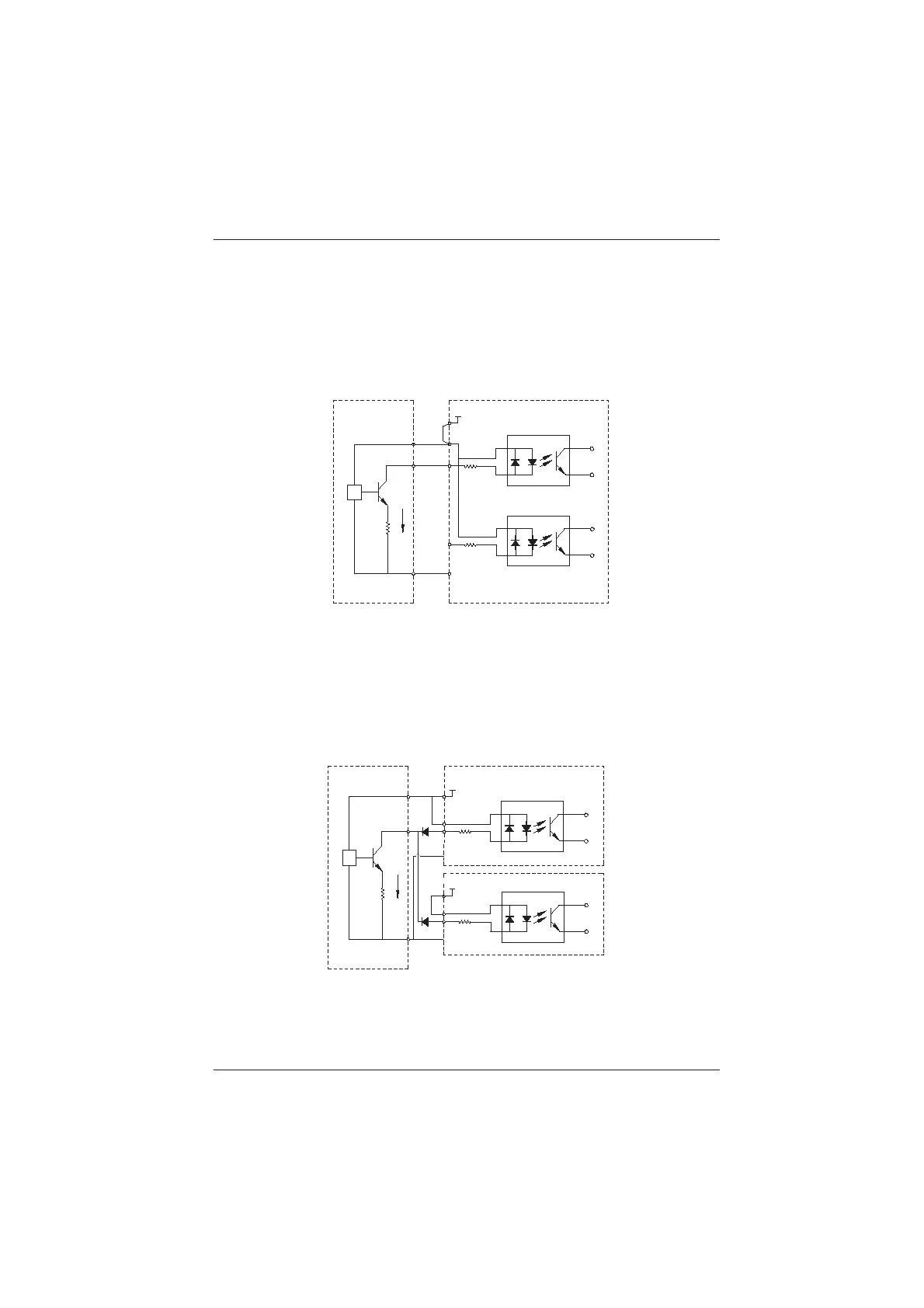
a˅ SINK wiring
)LJXUH:LULQJLQ6,1.PRGH
0V
DI5
DI1
23
+24V
+24V
2.4k
2.4k
3.3ȍ
NPN
Signal
External controller
AC drive control board
+VCC
&20
This is the most commonly used wiring mode. To apply external power supply, remove
WKHMXPSHUEHWZHHQ9DQG23DQGWKHMXPSHUEHWZHHQ&20DQG&0(DQG
FRQQHFWWKHSRVLWLYHSROHRIH[WHUQDOSRZHUVXSSO\WR23DQGQHJDWLYHSROHWR&0(
In such wiring mode, the DI terminals of different AC drives cannot be connected in
SDUDOOHO2WKHUZLVH',PDOIXQFWLRQPD\UHVXOW,ISDUDOOHOFRQQHFWLRQGLIIHUHQW$&
drives) is required, connect a diode in series at the DI and the diode needs to satisfy
WKHUHTXLUHPHQW,)!P$8)9
Figure 3-18 DI terminals connected in parallel in SINK mode
0V
DI1
23
+24V
+24V
2.4k
3.3ȍ
NPN
Signal
External controller
AC drive control board 2
+VCC
&20
DI1
23
+24V
2.4k
AC drive control board 1
&20
efesotomasyon.com
 Loading...
