Operation, Display and Application Examples
MD380 User Manual
- 66 -
$,8VHGDVWKH)UHTXHQF\6RXUFH
The AI terminal can be used as the frequency source. The MD380 provides two
$,WHUPLQDOV$,DQG$,RQWKHFRQWUROERDUGDQGWKHRSWLRQDO,2H[WHQVLRQFDUG
provides another AI terminal (AI3).
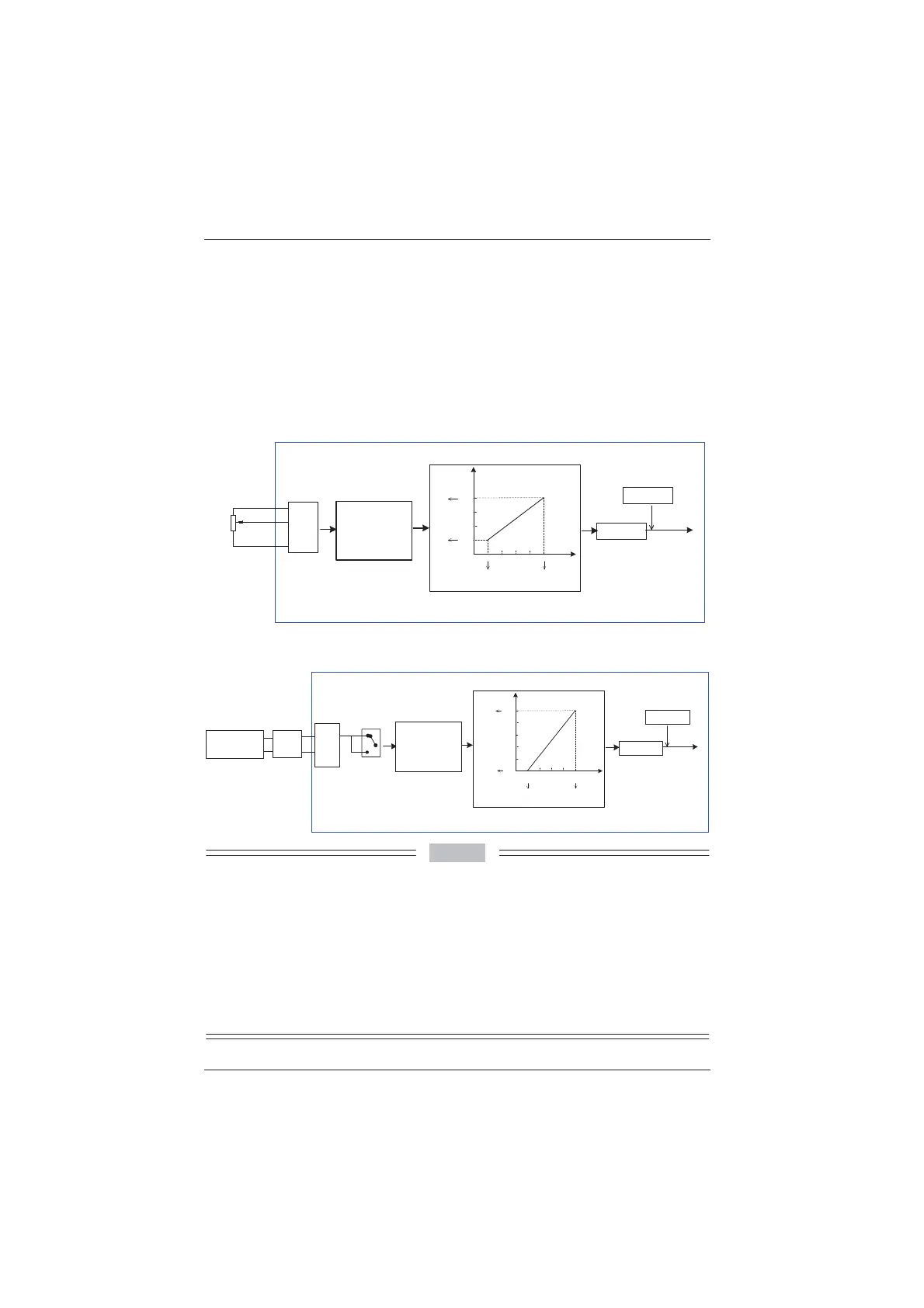
7KHIROORZLQJ¿JXUHVVKRZKRZWRXVHWKH$,DVWKHIUHTXHQF\VRXUFH
Figure 4-20 Voltage input of AI1 connected to the potentiometer as the frequency
source (2–10 V corresponding to 10–40 Hz)
F4-13 0.00 V
F4-14 0.0%
F4-15 10.00 V
F4-16 100%
F4-17 0.1s
F0-03 2
Frequency
reference
Terminal
Function code
(default value)
10V
AI1
.
GND
Frequency source
selection
F0-07 0
Analog setting
Frequency
feature setting
F4-13 to F4-17: relationship between
AI1 setting and corresponding value
1
2
3
0-10 VDC
Potentiometer
2 kȍ
Default:
0-10 V corresponding to 0-50 Hz
F4-33: AI curve selection
AI
Corresponding
setting
80.0
60.0
40.0
20.0
0.0
0
2.00 4.00 6.00 8.00 10.00
F4-13
F4-14
F4-16
F4-15
2-10 V corresponding to 10-40 Hz
F0-10 50.00 Hz
F4-33 1
0.0
8QLW: V
8QLW: %
Figure 4-21 Current input of AI2 connected to 4DA module of the PLC as the frequency
source (4–20 mA corresponding to 0–50 Hz)
F0-03 2
Frequency
reference
Terminal
Function code
(default value)
Frequency
source selection
F0-07 0
Frequency
feature setting
F4-18 to F4-22: relationship between AI1
setting and corresponding value
Default:
0-10 V corresponding to
0-50 Hz
F4-33: AI curve selection
F4-18 0.00 V
F4-19 0.0%
F4-20 10.00 V
F4-21 100%
F4-22 0.1s
AI
20.0
F4-18
F4-19
F4-20
0-20 mA corresponding to 0-50 Hz
F0-10 50.00 Hz
16.012.08.0
4.0
F4-33 10
100.
0
F4-21
0
80.0
60.0
40.0
20.0
0.0
Corresponding
setting
8QLW: mA
8QLW: %
V
I
Selection
using
jumper J8
AI2
GND
Analog setting
Selection using
jumper J8
I: AI2 current input
V: AI2 voltage input
PLC
4D/A module
$2
GND
Note: Select the analog input type based
on the output type of the D/A module.
10.00 V2.00 V
Note
0'SURYLGHVWZR$,WHUPLQDOV$,DQG$,RQWKHFRQWUROERDUGDQGWKHRSWLRQDO,2
extension card provides another AI terminal (AI3).
2. AI1 provides 0–10 V voltage input. AI2 provides 0–10 V voltage input or 4–20 mA current input,
determined by jumper J8 on the control board. AI3 provides -10 V to +10 V bipolar voltage input.
:KHQ$,LVXVHGDVWKHIUHTXHQF\VRXUFHRIWKHYROWDJHRUFXUUHQWLQSXWFRUUHVSRQGLQJ
setting corresponds to the maximum frequency in F0-10.
:KHQWKHWHPSHUDWXUHWUDQVPLWWHULVXVHGIRUDQDORJVHWWLQJLWPXVWEHFRQQHFWHGWR$,RQWKH
,2H[WHQVLRQFDUG
0'SURYLGHV¿YHFRUUHVSRQGLQJUHODWLRQVKLSFXUYHVZKLFKFDQEHVHOHFWHGLQ)7KH
input values and corresponding settings of each curve are set in F4-13 to F4-27 and group A6.
efesotomasyon.com
 Loading...
