T
Taylor ConwayAug 27, 2025
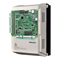
What causes undervoltage in Inovance Monarch 220-NICE-L-C-4011?
- TTodd ParrishAug 27, 2025
Undervoltage in your Inovance Controller can be caused by a few things. It could be due to an instantaneous power failure on the input power supply, so check whether the power fails during running and ensure the wiring of all power input cables is secure. The input voltage might also be too low, so check the external power voltage. In some cases, the drive control board might be failing.