2 Installation and Wiring
- 29 -
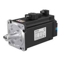
Table 2-4 Connectors of power cables on the motor side of IS810 series servo drive
Outline Drawing Terminal Pin Arrangement
Frame Size of
Matching Motor
MIL-DTL-5015 series 3108E20-18S aviation plug
"
)(
#
*
'
$%
&
New Structure Old Structure
Color
Pin No. Signal Pin No. Signal
B U B U Blue
I V I V Black
F W F W Red
G PE G PE
Yellow/
green
C
Brake signal
(Positive)
- - -
E
Brake signal
(Negative)
- - -
Size100
Size130
3 Connection to power cables of SV660 series servo drive
Figure 2-4 Diagram of connection between servo drive output terminals and the servo motor
 Loading...