6
NS-RNE4BWH8-C/NS-RNE4BMSS9-C/NS-RNEC4BSS9-C
www.insigniaproducts.com
Step 2 — Secure the bracket
The bracket must be screwed to either the FLOOR or REAR WALL.
FLOOR Installation:
WOOD FLOOR: Use the screws provided to secure the bracket using the pair of marked holes (either Loc A or B).
CONCRETE FLOOR: Using a concrete bit, drill a 5/32” pilot hole 2” (5 cm) deep into the concrete at the center of
each of the marked holes (either Loc A or B). Use the screws provided to secure the bracket to the floor.
REAR WALL Installation:
Use the 2 screws provided to secure the bracket using the pair of marked holes at Loc C. The screws MUST enter
into a wood sill plate. If the wall contains any metal studs or similar materials, then the floor must be used.
Step 3 — Check the bracket
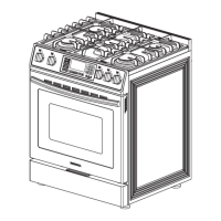
After installing the bracket, slide the range into its final location. The rear leveling leg must be fully inserted into
the ANTI-TIP bracket. If the range has a storage drawer, remove the drawer and look underneath the range to see
if the leg is fully engaged in the bracket as shown in Step 1.
On models without storage drawer or kickpanel, verify the rear leveling leg is properly secured within the bracket
by carefully tipping the range forward. DO NOT tip the range more than 4 inches (10 cm). If the bracket does not
stop the range within 4 inches (10 cm), the bracket is NOT properly installed and MUST be reinstalled following
these instructions.
The anti-tip bracket must be PROPERLY INSTALLED and the rear leveling leg must be FULLY ENGAGED
into the bracket to prevent the range from tipping. NEVER remove the leveling legs. This will prevent the
range from being secured to the ANTI-TIP bracket properly.
4 – LEVEL THE RANGE
WARNING: Never completely remove the leveling leg as the range will not be secured to the anti-tip
device properly.
MODELS WITHOUT BAKING OR WARMING DRAWERS
1 Install the oven racks in the oven and position the range where it will be installed.
2 Check for levelness by placing a spirit level or a cup, partially filled with water, on one
of the oven racks. If using a spirit level, take two readings—with the level placed
diagonally first in one direction and then the other.
3 Remove the storage drawer, broiler drawer, or kick panel. The front leveling legs can be
adjusted from the bottom and the rear legs can be adjusted from the top.
4 Use an open-end or adjustable wrench to adjust the leveling legs until the range is level.
5 Replace the drawer or panel.
Attachment to Floor or Rear Wall
Screw must enter
wood or concrete
Bracket
Wall sill plate
Screw must enter wood
B
Both
A
C
Lower
range
Raise
range
Front of range
Rear leveling legs
(on some models)
Front leveling legs
(on some models)
Adjust
from top
Lower
range
Raise
range
Leg
leveler
NS-RNE4BWH8-C_NS-RNE4BMSS9-C_NS-RNEC4BSS9-C_18-0194_Install MAN_V1_EN.fm Page 6 Wednesday, March 28, 2018 2:26 PM
 Loading...