14
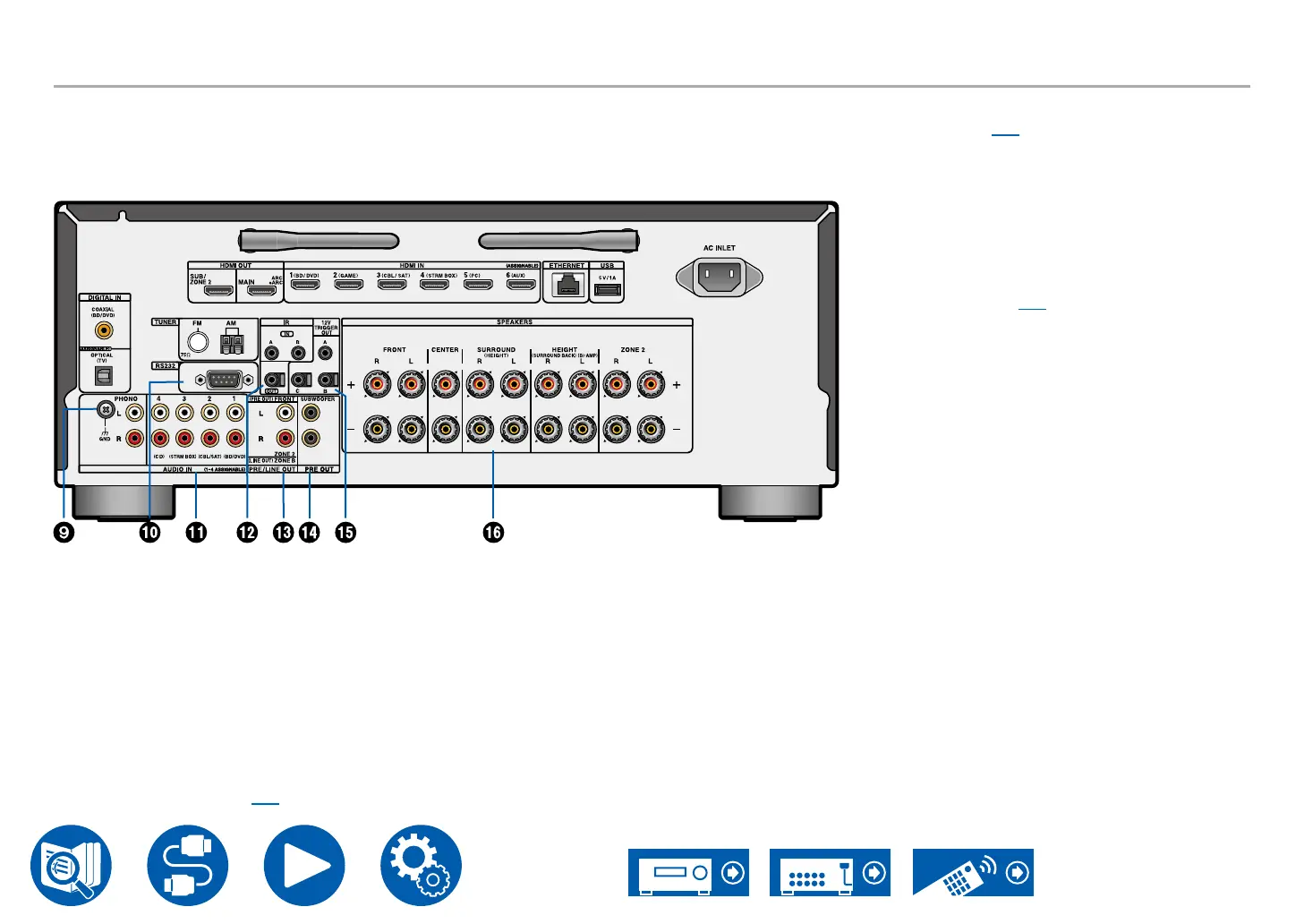
Rear Panel
9. GND terminal: Connect the ground wire of the
turntable.
10.
RS-232 port: Connect a home control system
equipped with an RS-232C port. For adopting
a home control system, contact the specialized
stores.
11.
AUDIO IN jacks: Input AV component audio
signals with an analog audio cable.
12.
IR IN A/B, IR OUT jacks: Connect a remote
control receiver unit. ( →p56)
13.
ZONE 2 PRE/LINE OUT jacks: Output audio
signals with an analog audio cable connected
to an integrated amplier in a separate room
(ZONE 2).
ZONE B LINE OUT jacks: Simultaneously
output the same audio source as the speakers
(ZONE A) connected to this unit by connecting
this unit to wireless headphones, wireless
speaker transmitter, etc., using an analog audio
cable.
PRE OUT FRONT jacks: Connect to a power
amplier. ( →p46)
14.
SUBWOOFER PRE OUT jacks: Connect a
powered subwoofer with a subwoofer cable.
Up to two powered subwoofers can be
connected. The same signal is output from each
SUBWOOFER PRE OUT jack.
15.
12V TRIGGER OUT A/B/C jack: Connect a
device equipped with a 12V trigger input jack to
enable power link operation between the device
and this unit. ( →p57)
16.
SPEAKERS terminals: Connect speakers with
speaker cables. (North American models support
banana plugs. Use a plug 4 mm in diameter. Y
plug connection is not supported.)