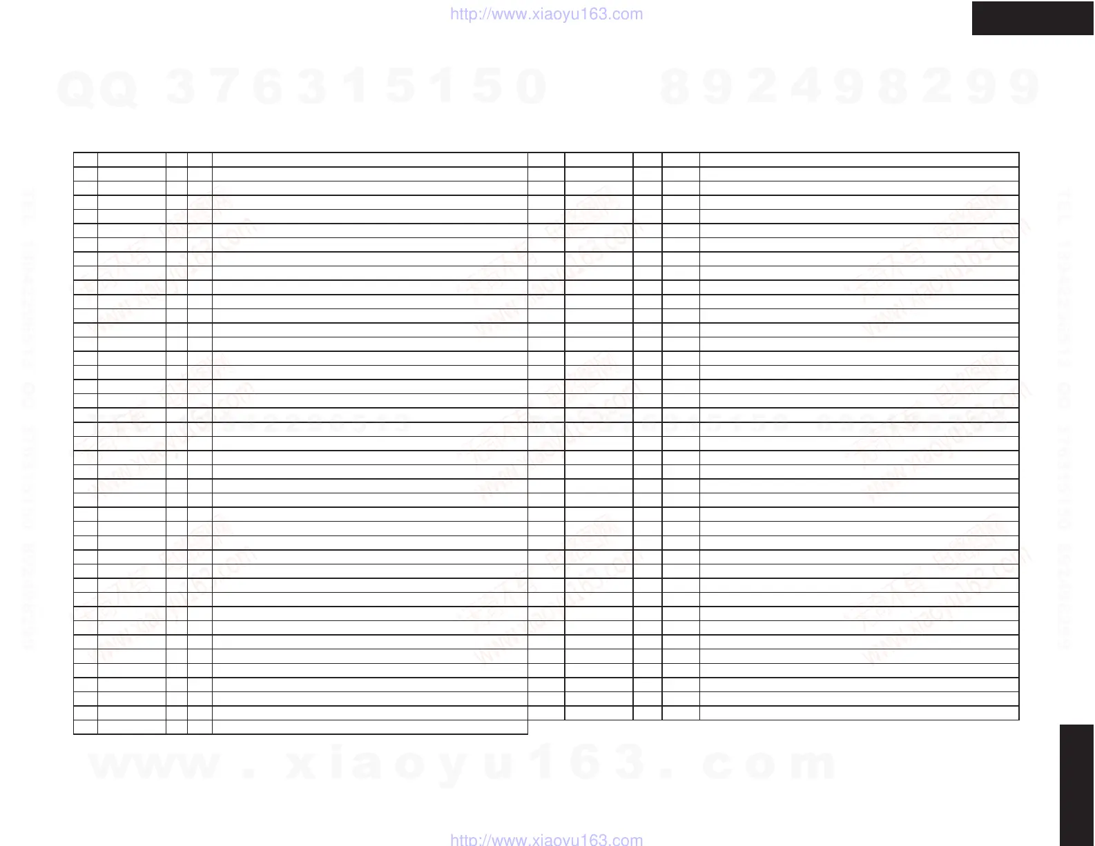
DTR-8.2
MAIN MICROPROCESSOR
Terminal Descriptions
DTR-8.2
No. Function I/O Act. Description No. Function I/O Act. Description
8 BYTE I Input pin to change the width of external data bus. Connect to Vss. 52 ADR152 O H Signal output pin to control address 15 of flash memory for second DSP.
9 CNVSS I Input pin to change the processor mode. Connect to Vss. 53 ADR162 O H Signal output pin to control address 16 of flash memory for second DSP.
12 ~RESET I Reset pin of microprocessor 54 ADR172 O H Signal output pin to control address 17 of flash memory for second DSP.
13 XOUT O Output pin of main clock oscillator 55 DFSDAC O H DAC sampling control output pin.
14 VSS I Ground pin 56 ~DARST O L Reset output pin for six channels DAC.
15 XIN I Input pin of main clock oscillator 57 ~CODECPD O L Reset output pin for CODEC IC.
16 VCC I Power supply pin. Apply 5V. 58 DFSCO O H Sampling frequency control output pin for CODEC IC.
18 PRTCTV I H Abnormal voltage/current detection input pin from protection circuit 62 VCC I Power supply pin. Apply 5V.
19 RDSSCK I CLK Modulator clock signal input pin from RDS decoder IC. 64 VSS I Power supply pin. Connect to ground,
20 ~POFF I L Input pin from detection circuit of power failure 68 TRG12A O H Output pin A to control the 12V trigger circuit.
21 ~PRTCTTHM I L Input pin from thermal detector circuit. 69 TRG12B O H Output pin B to control the 12V trigger circuit.
22 SEC1H O H Output terminal to change voltage of main amplifier. 70 TRG12Z O H Output pin to control the 12V trigger circuit of zone 2.
23 INT0 I H Input terminal from interrupter output of DIR IC. 71 SPRLZ2 O H Output pin to control the speaker relay of zone 2.
24 INT1 I H Output terminal to interrupter input of DIR IC. 72 SLRLF O H Output pin to control the speaker relay.
25 (DSPWRITE) I L Input port for check when DSP flash write. 73 POWER O H Output pin to control the relay of power source.
26 DIGSO O H Serial data output pin to DSP,DIR,DAC, nd Digital input ICs. 74 PLLCE O H Latch data output pin to PLL IC.
27 DIGSI I H Serial data input pin from DSP, and DIR ICs. 75 TUMUT O H Muting control output pin for tuner block.
28 DIGSCK O CLK Serial clock output pin to DSP,DIR,DAC,Digital input ICs. 76 ~SD I L Signal detection input pin from tuner section.
29 ~INTRQ1 I L INTRQ input pin from DSP IC 2(CS49329) 77 ~STEREO I L Stereo broadcast detection input pin.
30 ~INTRQ2 I L INTRQ input pin from DSP IC 1(CS49300) 78 RDSDATA I H Data input pin from RDS demodulator IC.
32 ~SUBRESET O L Reset signal output pin to sub-microprocessor. 79 RDSSIG I H Check signal input pin of RDS demodulator IC.
33 ~SUBPOFF O L Output pin to connect to pin POFF of sub-microprocessor. 81 AMUT O H Muting control output pin for audio circuit.
34 ~SUBREQ I L Communication request input pin from sub-microprocessor. 82 Z2LMUT O H Muting control output pin for line of zone 2.
35 MAINSO O H Serial data output pin to sub-microprocessor. 83 Z2MUT O H Muting control output pin for zone 2.
36 MAINSI I H Serial data input pin from sub-microprocessor. 84 VPCLK O H Serial clock output pin to electrical volume and PLL IC,
37 MAINSCK O CLK Serial clock output pin for communication of main and sub-microprocessors. 85 VPDATA O H Serial data output pin to electrical volume and PLL IC,
38 ~MAINREQ O L Communication request output pin of main microprocessor. 86 VSTB O H Strobe output pin to electrical volume IC.
39 ~DIRCS O L Chip select output pin of DIR IC, 87 TCS2 O L Chip select output pin to tone control IC of surround and center channels.
40 ~DIRRST O L Reset signal output pin to DIR IC, 88 TCS1 O L Chip select output pin to tone control IC of front channel..
41 Writing port of flash memory IC. 89 TDATA O H Serial data output pin to tone control IC.
42 ~DSPRST1 O L Reset signal output pin to DSP IC 2. 90 TCLK O CLK Serial clock output pin to tone control IC.
43 ~DSPCS1 O L Chip select output pin to DSP IC 1. 91 FSTB O H Strobe output pin to function switch ICs.
44
FMEM/SRAM1
O H Memory select output pin to RAM. 92 FDATA O H Serial data output pin to function switch ICs.
45
ADR151
OHSi
nal output pin to control address 15 of flash memory for first DSP. 93 FCL
OCL
Serial clock output pin to function switch ICs.
46 Port to write the flash memory IC. 94 HPMUT O H Muting control output pin for headphone circuit.
47 ADR161 O H Signal output pin to control address 16 of flash memory for first DSP. 96 VSS I Power supply pin for A/D converter. Connect to ground.
48 ADR171 O H Signal output pin to control address 17 of flash memory for first DSP. 97 VOLH I H Measurement input pin of main amplifier output.
49 ~DSPRST2 O
㧸
Reset output pin to DSP IC 2. 98 VREF I Reference voltage input pin for A/D converter.
50 ~DSPCS2 O L Chip select output pin to DSP IC 2. 99 VCC I Power supply pin for A/D converter. Apply 5V.
51
FMEM/SRAM2
OH
2nd DSP memory select output pin.L=FLASH,H=SRAM
w
w
w
.
x
i
a
o
y
u
1
6
3
.
c
o
m
Q
Q
3
7
6
3
1
5
1
5
0
9
9
2
8
9
4
2
9
8
T
E
L
1
3
9
4
2
2
9
6
5
1
3
9
9
2
8
9
4
2
9
8
0
5
1
5
1
3
6
7
3
Q
Q
TEL 13942296513 QQ 376315150 892498299
TEL 13942296513 QQ 376315150 892498299
http://www.xiaoyu163.com
http://www.xiaoyu163.com