EN – ENGLISH
76
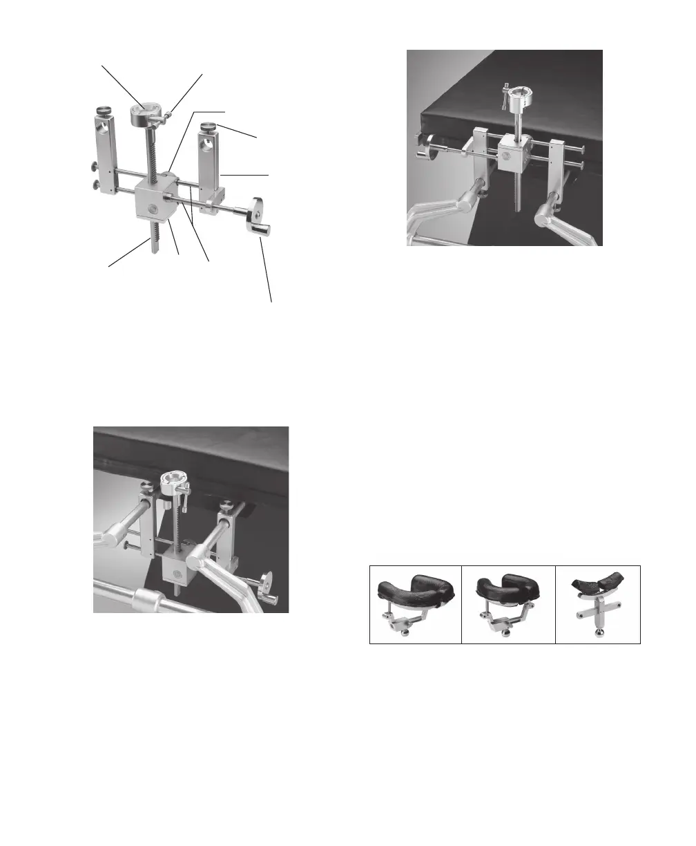
Post Screw
Posts
Crank Handle
Crossbars
Gear Box
Socket Sha
Locking Knob
Socket T-Knob
Socket
Figure 2
Figure 3
NOTE:
The Coupler is typically positioned with the Locking Knob
toward the O.R. Table, but may be reversed if necessary.
The Coupler may also be inverted to place the Gear Box
higher if required. (Figure 4)
Figure 4
3. Lock the handles on the O.R. Table to secure the Base
Unit. Slide Coupler to desired location and lock the
Hold Down Screws.
4. In order to raise or lower the Infinity Socket position,
turn the Crank Handle on the Gear Box (Figure 2) clock-
wise or counterclockwise. To make lateral adjustments
slide the Gear Box le or right on the Crossbars. To
secure these positions, tighten the Locking Knob.
The Locking Knob secures the Gear Box from moving
in any direction and prevents the Crank Handle from
movement.
Mount the Headrest to the Coupler
Three styles of headrests are available:
Horseshoe-Adult
(419A1031)
Horseshoe-Pediatric
(419A1030)
General Purpose
(419A1050)
Replacement Gel Pads are available:
Pediatric - Le 440C1011 1 ea
Pediatric - Right 440C1012 1 ea
Adult - Le 41C1444 1 ea
Adult - Right 41C1445 1 ea
Mini (for General Purpose) 419A1048 2 ea