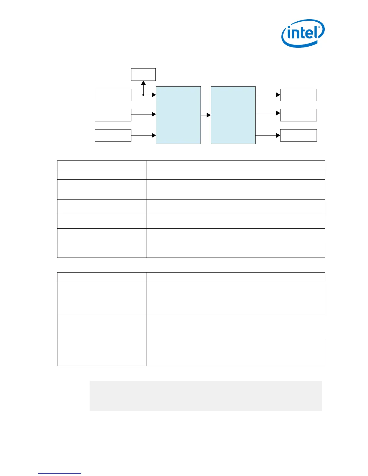
Figure 11. Intel FPGA HDMI IP Core Simulation Testbench Block Diagram
Video data
Audio data
Aux data
CRC Check
CRC Check
Audio Data Check
Aux Data Check
HDMI RXHDMI TX
Video TPG
Audio Sample Gen
Aux Sample Gen
Table 24. Testbench Components
Component Description
Video TPG The video test pattern generator (TPG) provides the video stimulus.
Audio Sample Gen The audio sample generator provides audio sample stimulus. The generator
generates an incrementing test data pattern to be transmitted through the audio
channel.
Aux Sample Gen The aux sample generator provides the auxiliary sample stimulus. The generator
generates a fixed data to be transmitted from the transmitter.
CRC Check This checker verifies if the TX transceiver recovered clock frequency matches the
desired data rate.
Audio Data Check The audio data check compares whether the incrementing test data pattern is
received and decoded correctly.
Aux Data Check The aux data check compares whether the expected aux data is received and
decoded correctly on the receiver side.
The HDMI simulation testbench does the following verification tests:
HDMI Feature
Verification
Video data • The testbench implements CRC checking on the input and output video.
• It checks the CRC value of the transmitted data against the CRC calculated in
the received video data.
• The testbench then performs the checking after detecting 4 stable V-SYNC
signals from the receiver.
Auxiliary data • The aux sample generator generates a fixed data to be transmitted from the
transmitter.
• On the receiver side, the generator compares whether the expected auxiliary
data is received and decoded correctly.
Audio data • The audio sample generator generates an incrementing test data pattern to
be transmitted through the audio channel.
• On the receiver side, the audio data checker checks and compares whether
the incrementing test data pattern is received and decoded correctly.
A successful simulation ends with the following message:
# SYMBOLS_PER_CLOCK = 2
# VIC = 0
# AUDIO_CLK_DIVIDE = 800
# TEST_HDMI_6G = 1
# Simulation pass
2 Intel FPGA HDMI Design Example Detailed Description
UG-20077 | 2017.11.06
Intel
®
FPGA HDMI Design Example User Guide for Intel
®
Arria 10 Devices
39
 Loading...


