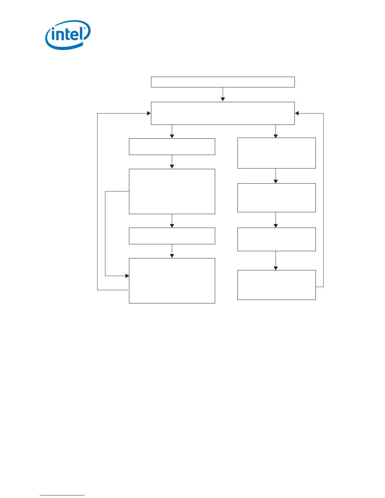
Figure 8. Reconfiguration Sequence Flow
The figure illustrates the Nios II software flow that involves the controls for I
2
C master and HDMI source.
The Nios II processor commands the I C master
to send SCDC information.
Reconfiguration Required
Measure Valid Received A TX Hot-Plug Event Occured
Reconfiguration
Not Required
Poll periodic measure valid signal from RX rata detection circuit to determine
whether TX reconfiguration is required. Also, poll the TX hot-plug request to
determine whether a TX hot-plug event has occured.
Reset the TX HDMI PLL and TX transceiver. Initialize the I C Master Controller Core.
2
Retrieve the clock frequency band based on
the measure and TMDS_Bit_clock_Ratio
values and read the color depth information
from the HDMI sink to determine whether
TX HDMI PLL and TX transceiver
reconfiguration and oversampling is required.
Read TMDS_Bit_clock_Ratio value from
the HDMI sink and measure value.
Nios II processor sends sequential commands
to reconfigure the TX HDMI PLL and TX
transceiver (followed by recalibration on
Intel Arria 10 device), and reset sequence after
reconfiguration. It then sends a reset to the
HDMI TX core.
Deassert edid_ram_access control signal
to enable the HDMI RX Top to trigger a
hotplug detect event to the external
HDMI source.
Assert HDMI RX Top’s edid_ram_access
control signal to block HDMI sink’s EDID
RAM from being accessed by external
HDMI source.
Send TMDS_Bit_clock_Ratio and
Scrambler_Enable information to the
external HDMI sink’s SCDC registers
through the I C interface.
2
Read EDID from external sink through I C
interface and write the EDID content to
the HDMI RX EDID RAM.
2
2
2.3 Dynamic Range and Mastering (HDR) InfoFrame Insertion and
Filtering
The Intel FPGA HDMI design example includes a demonstration of HDR Infoframe
insertion in a RX-TX loopback system.
HDMI Specification version 2.0a allows Dynamic Range and Mastering InfoFrame to be
transmitted through HDMI auxiliary stream. In the demonstration, the Auxiliary Data
Insertion block supports the HDR insertion. You only need to format the intended HDR
Infoframe packet as specified in the module’s signal list table and use the provided
AUX Insertion Control module to schedule the insertion of the HDR infoframe once
every video frame.
In this example configuration, in instances where the incoming auxiliary stream
already includes HDR Infoframe, the streamed HDR content is filtered. The filtering
avoids conflicting HDR Infoframes to be transmitted and ensures that only the values
specified in the HDR Sample Data module are used.
2 Intel FPGA HDMI Design Example Detailed Description
UG-20077 | 2017.11.06
Intel
®
FPGA HDMI Design Example User Guide for Intel
®
Arria 10 Devices
20

 Loading...


