EasyManuals Logo

Intel D2550MUD2 Product Guide

Intel D2550MUD2
66 pages
To Next Page IconTo Next Page
To Previous Page IconTo Previous Page
Page #38 background imageLoading...
Page #38 background image
Intel Desktop Board D2550MUD2 Product Guide
38
Connecting to the TPM Header
The TPM header is shown in Figure 12, E. Table 11 shows the pin assignments and
signal names for TPM header.
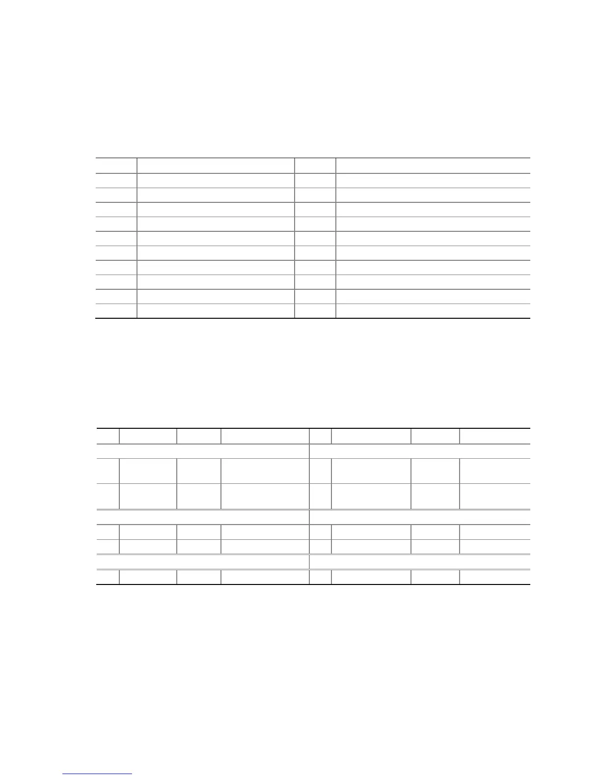
Table 11. TPM Header
Pin
Signal Name
Pin
Signal Name
1
TPM_HDR_CLK
2
Ground
3
LFRAME#
4
Key (no pin)
5
TPM_PLTRST#
6
No connection
7
LAD3/FWH3
8
LAD2/FWH2
9
+3.3 V
10
LAD1/FWH1
11
LAD0/FWH0
12
Ground
13
No connection
14
No connection
15
+3.3 VSB
16
SERIRQ
17
Ground
18
TPM_CLKRUN
19
LPC_PD#
20
No connection
Connecting to the Front Panel Header
Before connecting to the front panel header, observe the precautions in "Before You
Begin" on page 25. See Figure 12, F for the location of the front panel header.
Table 12 shows the pin assignments for the front panel header.
Table 12. Front Panel Header
Pin Signal In/Out Description Pin Signal In/Out Description
Hard Drive Activity LED
Power LED
1 HD_PWR Out
Hard disk LED pull-
up (330 ) to +5 V
2 HDR_BLNK_GRN Out
Front panel
green LED
3 HDA# Out
Hard disk active
LED
4 HDR_BLNK_YEL Out
Front panel
yellow LED
Reset Switch
On/Off Switch
5 Ground Ground 6 SWITCH_ON# In Power switch
7
FP_RESET#
In
Reset switch
8
Ground
Ground
Power Not Connected
9
+5 V
Power
10
N/C
No pin

Table of Contents

Other manuals for Intel D2550MUD2

Questions and Answers:

Question and Answer IconNeed help?

Do you have a question about the Intel D2550MUD2 and is the answer not in the manual?

Intel D2550MUD2 Specifications

General IconGeneral
BrandIntel
ModelD2550MUD2
CategoryMotherboard
LanguageEnglish

Related product manuals