Technical Reference
43
2.2.2.3 Power Supply Connectors
The board has the following power supply connectors:
• External Power Supply – the board can be powered through a 19 V DC connector
on the back panel. The back panel DC connector is compatible with a 5.5 mm/OD
(outer diameter) and 2.5 mm/ID (inner diameter) plug, where the inner contact is
+19 (±10%) V DC and the shell is GND. The maximum current rating is 10 A.
• Internal Power Supply – the board can alternatively be powered via the internal
19 V DC 1 x 2 power connector, where pin 1 is GND and pin 2 is +19 (±10%) VDC.
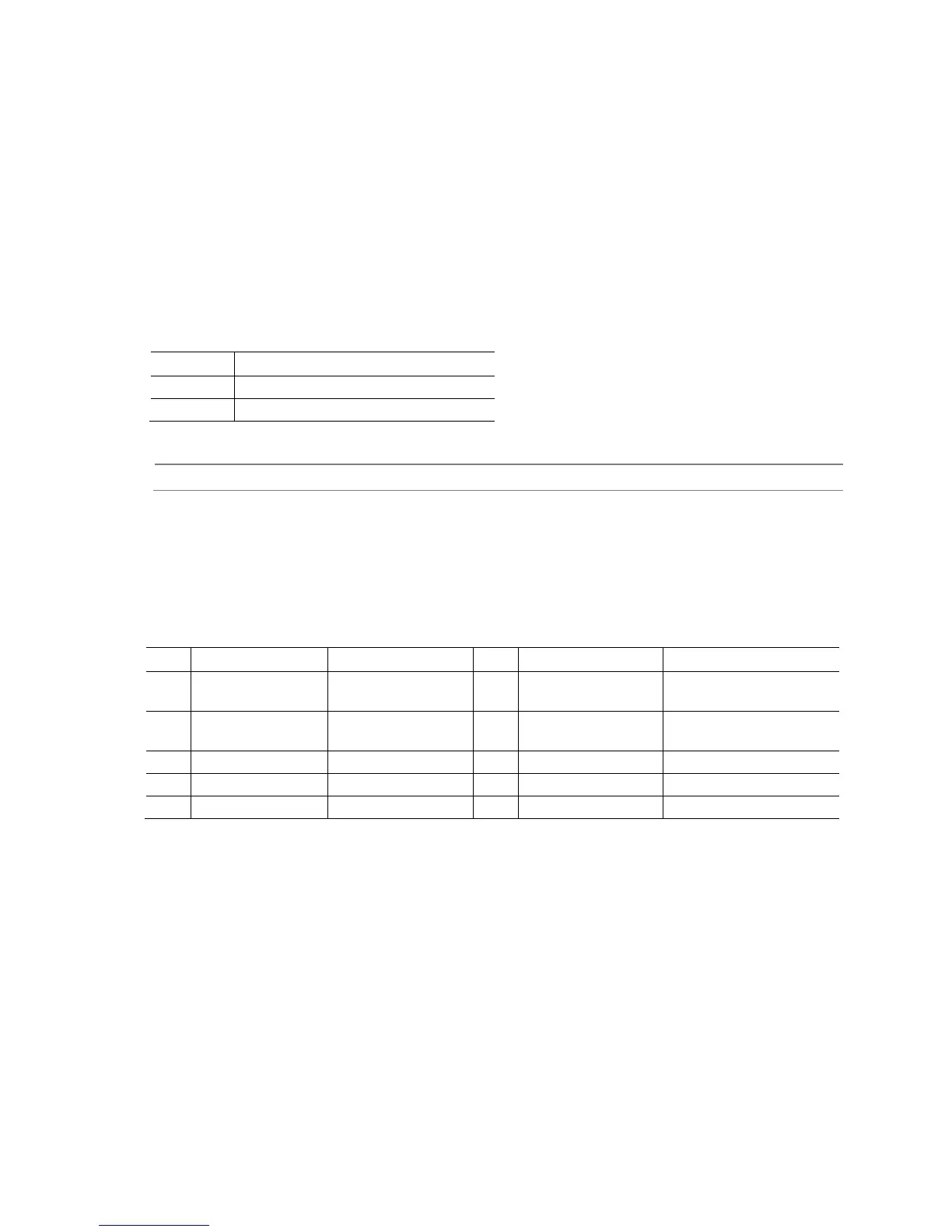
Table 14. 19 V Internal Power Supply Connector
Pin Signal Name
1 Ground
2 +19 V (±10%)
Power supply considerations Section 2.5.1, page 49
2.2.2.4 Front Panel Header
This section describes the functions of the front panel header. Table 15 lists the signal
names of the front panel header. Figure 11 is a connection diagram for the front panel
header.
Table 15. Front Panel Header
1 HDD_POWER_LED Pull-up resistor
(750 Ω) to +5V
2 POWER_LED_MAIN [Out] Front panel LED
(main color)
3 HDD_LED# [Out] Hard disk
activity LED
4 POWER_LED_ALT [Out] Front panel LED
(alt color)
5 GROUND Ground 6 POWER_SWITCH# [In] Power switch
7 RESET_SWITCH# [In] Reset switch 8 GROUND Ground
9 +5V_DC Power 10 Key No pin