Technical Reference
45
2.2.2.4.4 Power Switch Header
Pins 6 and 8 can be connected to a front panel momentary-contact power switch. The
switch must pull the SW_ON# pin to ground for at least 50 ms to signal the power
supply to switch on or off. (The time requirement is due to internal debounce circuitry
on the board.) At least two seconds must pass before the power supply will recognize
another on/off signal.
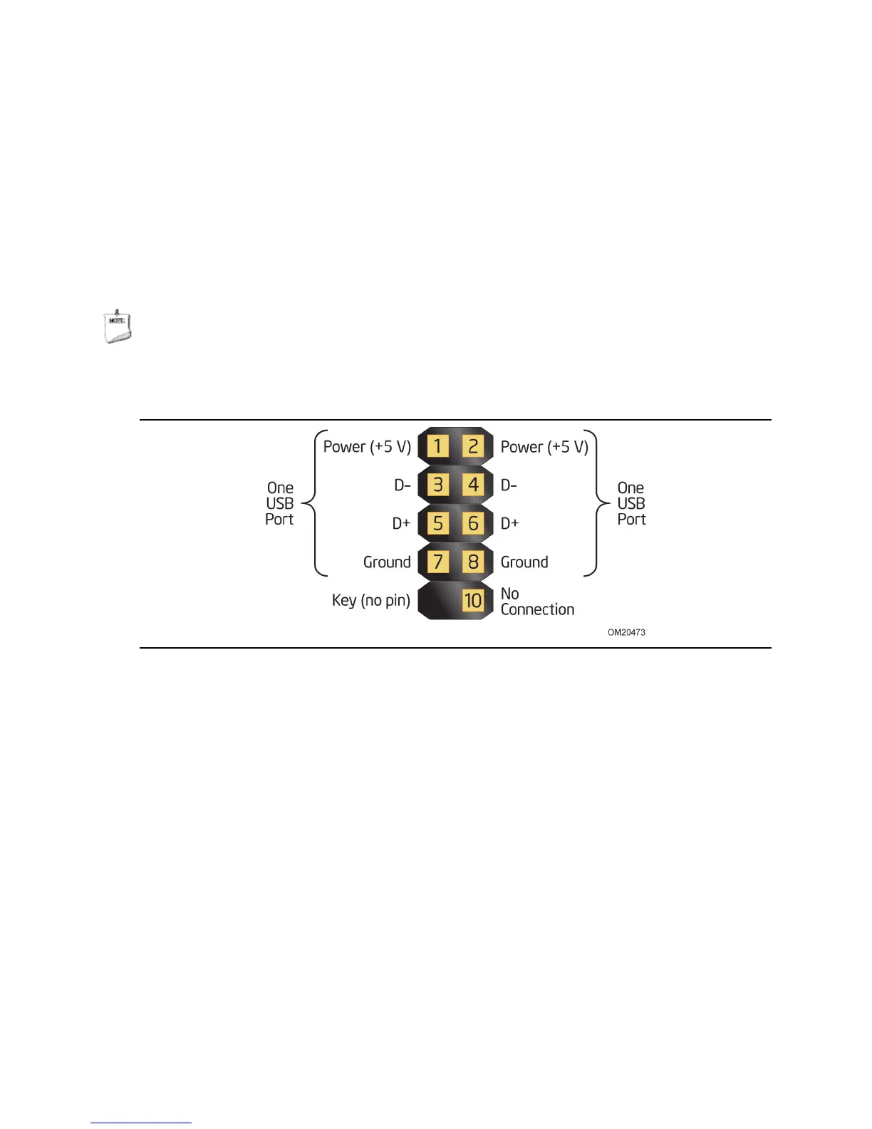
2.2.2.5 Front Panel USB 2.0 Header
Figure 12 is a connection diagram for the front panel USB 2.0 header.
NOTE
• The +5 V DC power on the USB header is fused.
• Use only a front panel USB connector that conforms to the USB 2.0 specification for
high-speed USB devices.
Figure 12. Connection Diagram for Front Panel
USB 2.0 Dual-Port Header