Contents
ix
5.1.5 ENERGY STAR* 5.2, e-Standby, and ErP Compliance ................. 78
5.1.6 Regulatory Compliance Marks (Board Level) ............................. 79
5.2 Battery Disposal Information .............................................................. 80
Figures
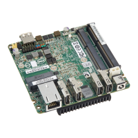
1. Major Board Components (Top) .......................................................... 13
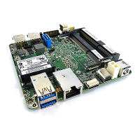
2. Major Board Components (Bottom) ..................................................... 15
3. Block Diagram .................................................................................. 17
4. Memory Channel and SO-DIMM Configuration ...................................... 21
5. LAN Connector LED Locations ............................................................. 27
6. Thermal Solution and Fan Header ....................................................... 29
7. Location of the Standby Power LED ..................................................... 34
8. Detailed System Memory Address Map ................................................ 36
9. Back Panel Connectors ...................................................................... 38
10. Connectors and Headers (Bottom) ...................................................... 39
11. Connection Diagram for Front Panel Header ......................................... 44
12. Connection Diagram for Front Panel USB 2.0 Dual-Port Header............... 45
13. Location of the BIOS Configuration Setup Jumper ................................. 46
14. Board Dimensions ............................................................................. 48
15. Localized High Temperature Zones ..................................................... 51