Intel Desktop Board DG31GL Product Guide
42
Connecting to the USB 2.0 Headers
Before connecting to the USB 2.0 headers, observe the precautions in "Before You
Begin" on page
23. See Figure 19, F on page 39 for the location of the three USB 2.0
headers.
Table 9 shows the pin assignments for each USB 2.0 header. Each USB
header can be used to connect two USB devices (A and B).
Table 9. USB 2.0 Header Signal Names
USB Port A USB Port B
Pin Signal Name Pin Signal Name
1 Power (+5 V) 2 Power (+5 V)
3 D- 4 D-
5 D+ 6 D+
7 Ground 8 Ground
9 Key 10 No Connection
Note: USB ports may be assigned as needed.
NOTE
Computer systems that have an unshielded cable attached to a USB port might not
meet FCC Class B requirements, even if no device or a low-speed USB device is
attached to the cable. Use a shielded cable that meets the requirements for a
full-speed USB device.
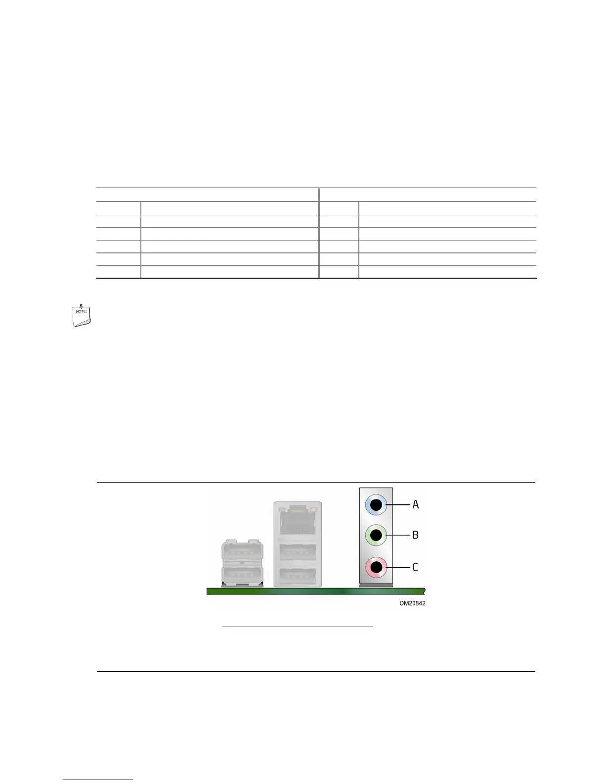
Connecting to the Audio System
After installing the audio driver from the Intel Express Installer CD-ROM, the multi-
channel audio feature can be enabled.
Figure 20 shows the back panel audio
connectors. The default connector assignments are shown in the figure.
Item Description
A Line In
B Line Out
C Mic In
Figure 20. Back Panel Audio Connectors
 Loading...