Installing and Replacing Desktop Board Components
45
Chassis Intrusion Header
Figure 19, C shows the location of the chassis intrusion header. This header can be
connected to a mechanical switch on the chassis to detect if the chassis cover is
removed. This switch should be in the open position when the chassis cover is
installed and closed when the cover is removed.
Table 7 shows the pin assignments and
signal names for the chassis intrusion header.
Table 7. Chassis Intrusion Header Signal Names
Pin Description
1 Intruder#
2 Ground
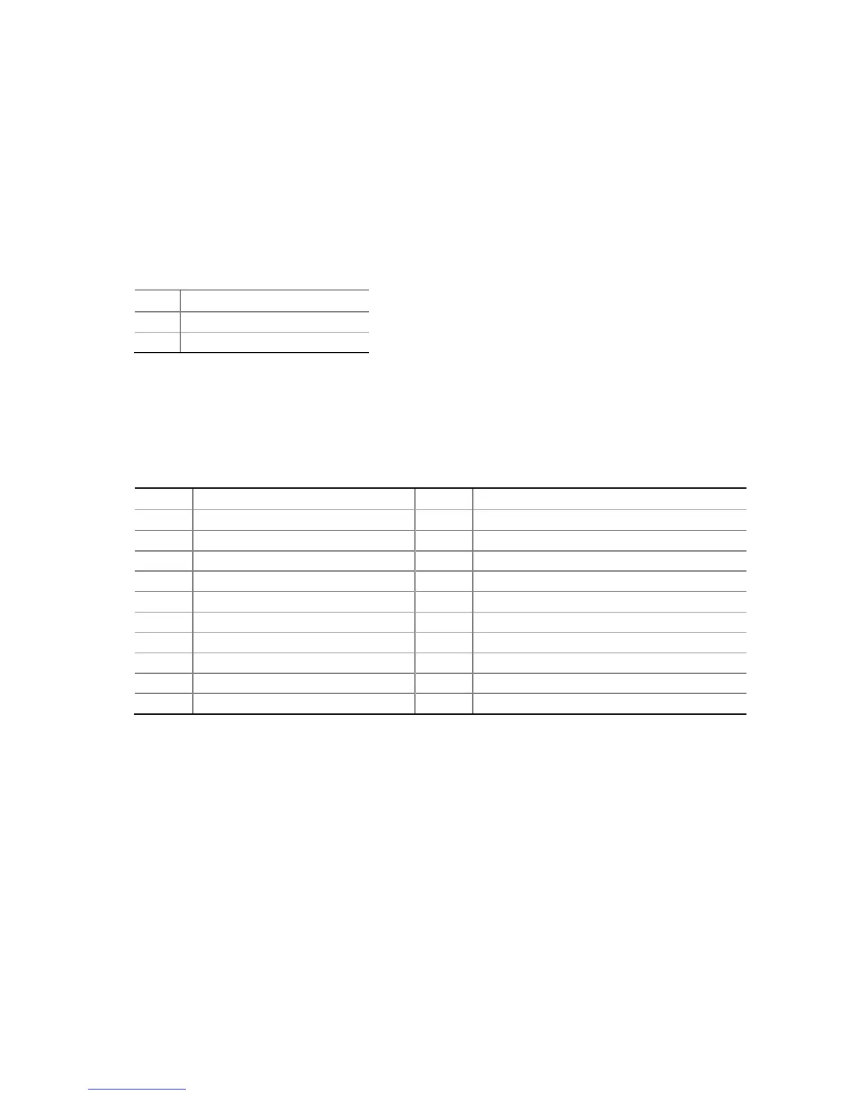
TPM Header
The TPM header is shown in Figure 19, D. Table 8 shows the pin assignments and
signal names for TPM header.
Table 8. TPM Header Signal Names
Pin Signal Name Pin Signal Name
1 CK_33M_TPM_DIP 2 Ground
3 LFRAME# 4 Key (no pin)
5 PLTRST# 6 No connection
7 LAD3 8 LAD2
9 +3.3 V 10 LAD1
11 LAD0 12 Ground
13 No connection 14 No connection
15 +3.3 VSB 16 TPM_SERRQ
17 Ground 18 TPM_CLKRUN#
19 LPCPD# 20 No connection

 Loading...


