Technical Reference
45
2.2.2.4.1 Hard Drive Activity LED Header
Pins 1 and 3 can be connected to an LED to provide a visual indicator that data is
being read from or written to an internal storage device. Proper LED function requires
a SATA hard drive or optical drive connected to an onboard SATA connector.
2.2.2.4.2 Reset Switch Header
Pins 5 and 7 can be connected to a momentary single pole, single throw (SPST) type
switch that is normally open. When the switch is closed, the board resets and runs the
POST.
2.2.2.4.3 Power LED Header
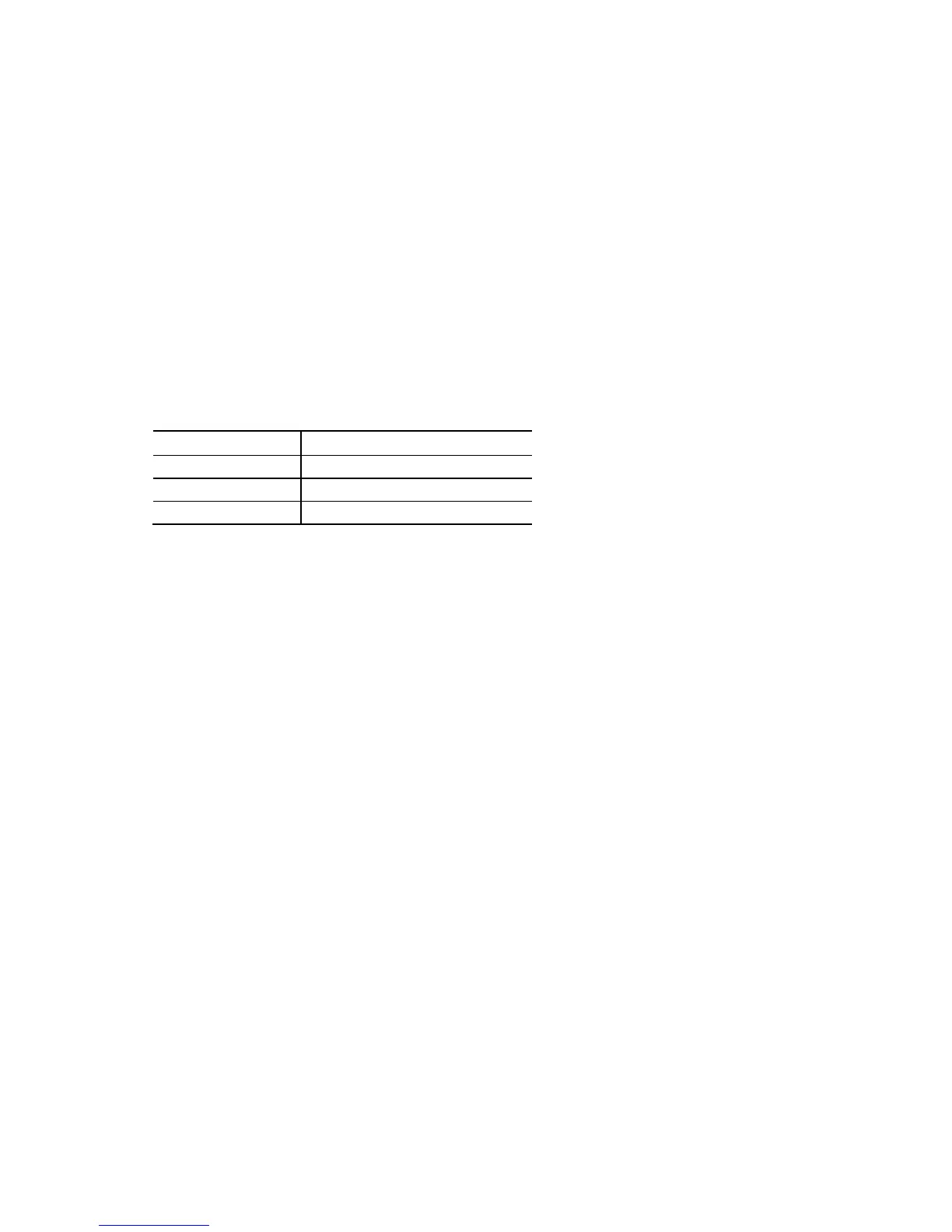
Pins 2 and 4 can be connected to a one- or two-color LED. Table 21 shows the default
states for this LED. More options are available through BIOS setup.
Table 21. States for a One-Color Power LED
LED State Description
Off Power off/sleeping
Steady Lit Running
Blink Standby
2.2.2.4.4 Power Switch Header
Pins 6 and 8 can be connected to a front panel momentary-contact power switch. The
switch must pull the SW_ON# pin to ground for at least 50 ms to signal the power
supply to switch on or off. (The time requirement is due to internal debounce circuitry
on the board.) At least two seconds must pass before the power supply will recognize
another on/off signal.