Intel Desktop Board DH77DF Technical Product Specification
48
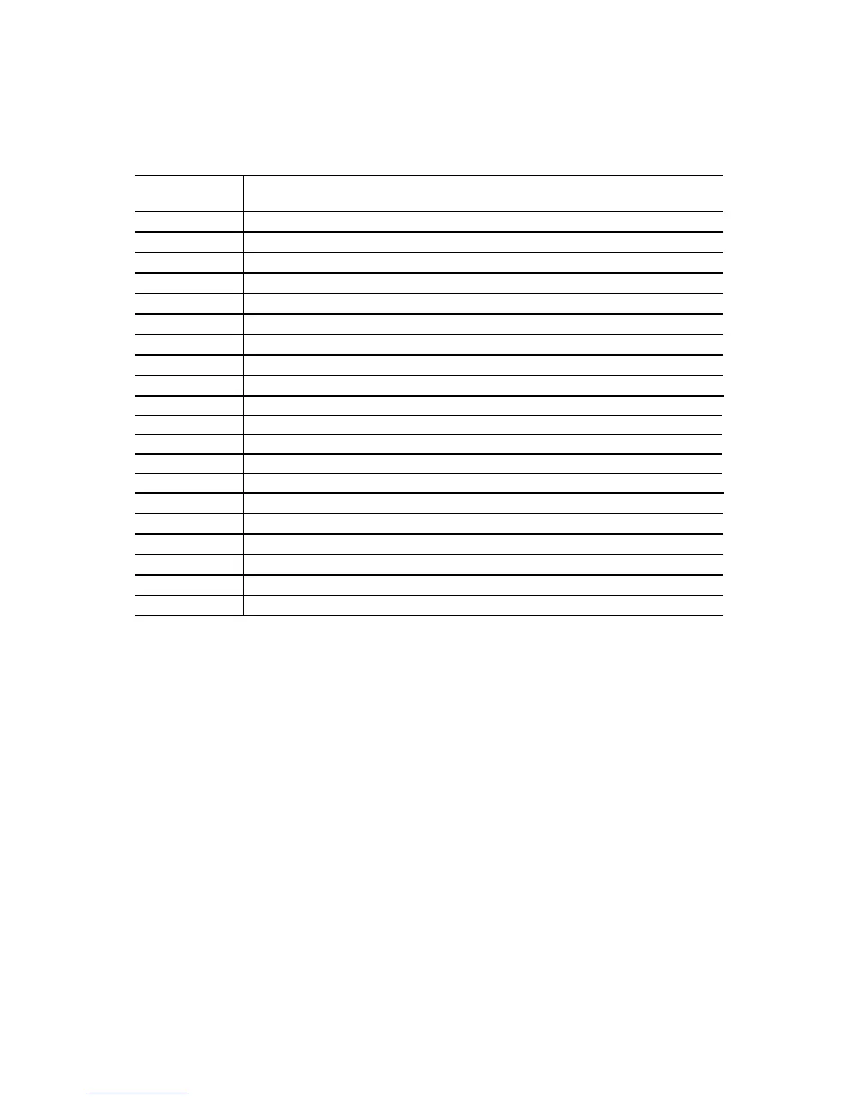
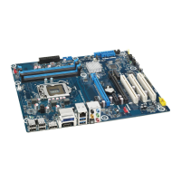
Table 15 lists the component-side connectors and headers
identified in Figure 11.
Table 15. Component-side Connectors and Headers Shown in Figure 11
Item/callout f
rom Figure 11
Des
cription
A IEEE 1394a front panel header (blue)
B SATA 3.0 Gb/s connectors (black)
C SATA 6.0 Gb/s connectors (blue)
D Front panel header
E Front panel USB 2.0 header
F Front panel USB 3.0 connector (blue)
G Alternate front panel power LED header
H Main power connector (2 x 12)
I Front panel USB 2.0 high-current charging header (orange)
J PCI Express Full-/Half-Mini Card slot
K Processor fan header
L Consumer IR transmitter (output) header (white)
M HTPC header (white)
N Consumer IR receiver (input) header (white)
O S/PDIF out header (yellow)
P PCI Express x16 bus add-in card connector
Q 12 V processor core voltage connector (2 x 2)
R Chassis intrusion header
S System fan header
T Front panel audio header (yellow)