Intel Desktop Board DZ68BC Technical Product Specification
56
Table 25. Serial Port Header
Pin Signal Name Pin Signal Name
1 DCD (Data Carrier Detect) 2 RXD# (Receive Data)
3 TXD# (Transmit Data) 4 DTR (Data Terminal Ready)
5 Ground 6 DSR (Data Set Ready)
7 RTS (Request to Send) 8 CTS (Clear to Send)
9 RI (Ring Indicator) 10 Not connected
Table 21. Alternate Power LED
Pin Signal Name
1 MAIN_COLOR_LED
2 KEY (no pin
3 ALT_COLOR_LED
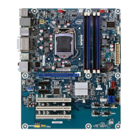
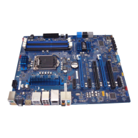
2.2.2.2 Add-in Card Connectors
The board has the following add-in card connectors:
• PCI Express 2.0 x16: two PCI Express 2.0 x16 connectors supporting simultaneous
transfer speeds up to 8 GB/s of peak bandwidth per direction and up to 16 GB/s
concurrent bandwidth.
• PCI Express 2.0 x1: two PCI Express 2.0 x1 connectors. The x1 interface supports
simultaneous transfer speeds up to 1 GB/s of peak bandwidth per direction and up
to 2 GB/s concurrent bandwidth.
• Conventional PCI (rev 2.3 compliant) bus: three Conventional PCI bus add-in card
connectors.
Note the following considerations for the Conventional PCI bus connector:
• The Conventional PCI bus connectors are bus master capable.
• SMBus signals are routed to the Conventional PCI bus connectors. This enables
Conventional PCI bus add-in boards with SMBus support to access sensor data on
the desktop board. The specific SMBus signals are as follows:
The SMBus clock line is connected to pin A40.
The SMBus data line is connected to pin A41.