11
The center of the screen shows the preview video of the mounted payload. All symbols and icons shown here are created
by the camera, and do not have any touch functionality. In the shown example, it is the Sony A7R*. Please refer to the Sony*
camera manual for further information, which can be accessed online:
https://esupport.sony.com/US/p/modelhome.pl?mdl=ILCE7R&LOC=3#/manualsTab
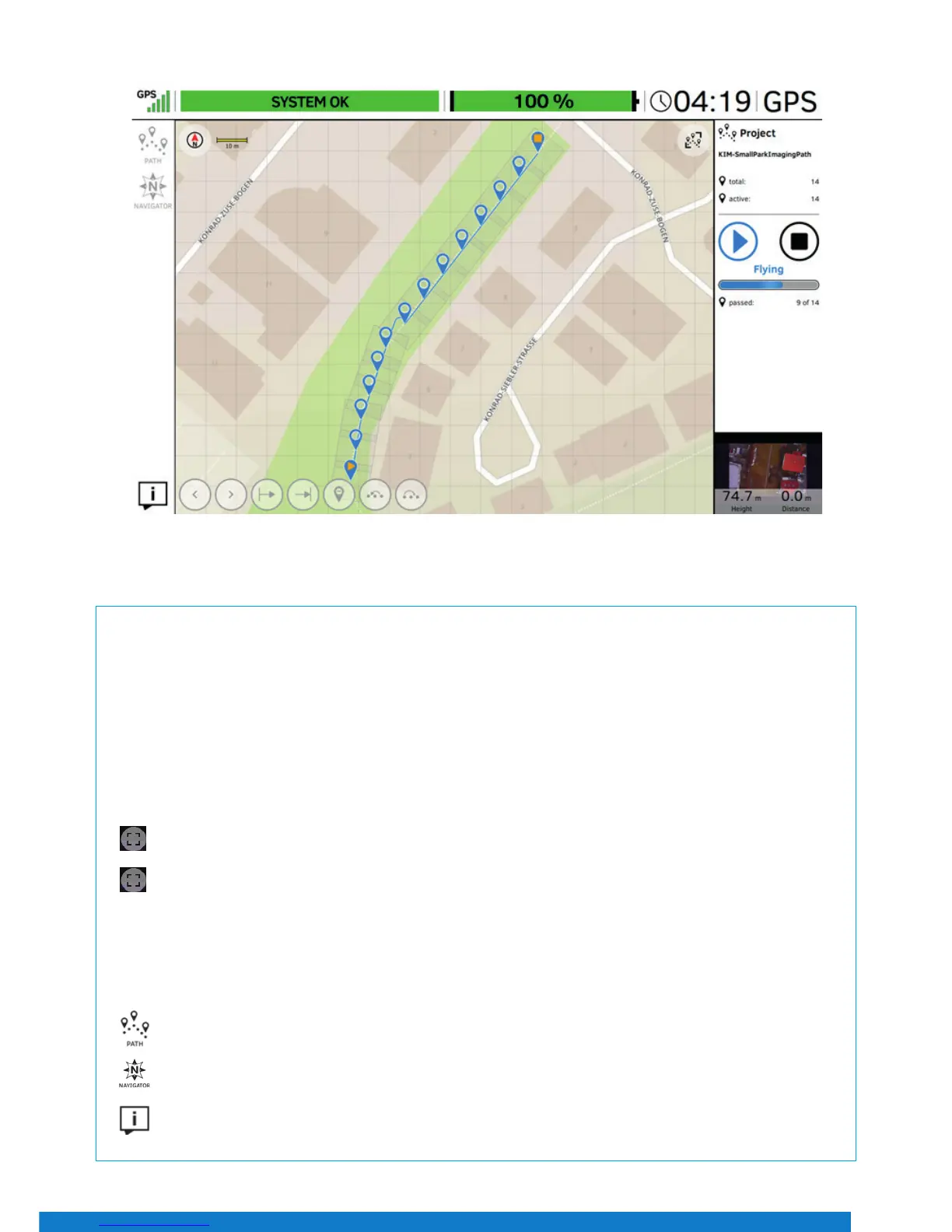
In the status line at the top of this window, general ight information is given.
On the top left corner under “GPS”, the quality of the GPS signal can be seen, indicated by 1 to 5 bars.
Next to the right of the window is the place for UAS messages. If everything is ne, SYSTEM OK is mentioned in a green bar. In
case there are warnings, the eld will turn red and display the respective warning.
Next to the UAS messages is another green bar which indicates the remaining battery capacity as a percentage, followed by
the actual performed ight time and the selected ight mode (GPS).
Tapping the button in the top right corner displays the preview video in full screen mode.
Tapping again will revert to the previous view.
In the lower right corner is more ight information, which refers to the UAV: Orientation, Height, and Distance from the take-
o point. Tapping that eld will toggle the view between the video preview and a map view (in case a map has been loaded
from an AscTec Navigator project). Please go to www.intel.com/Falconmanual to learn more about the AscTec Navigator.
In the left top corner (under GPS) are buttons for two dierent functions:
Tapping the PATH button opens the PATH function, where ight paths can be stored and edited.
Tapping the NAVIGATOR button opens the NAVIGATOR window, where AscTec Navigator projects can be loaded
and own.
Tapping this button opens a window which gives information about the software (version, available updates, etc.).
Main Screen
Figure 21