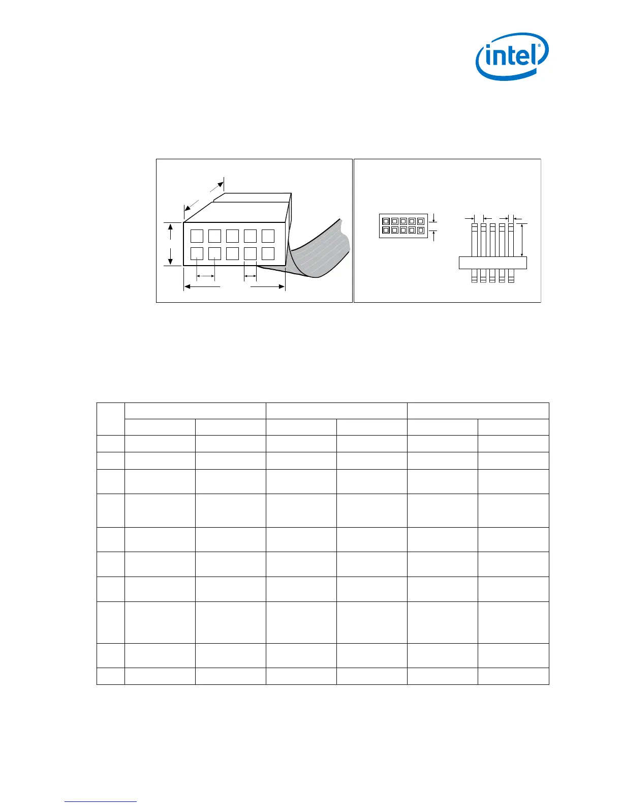
A 10-pin surface mount header can be used for the JTAG, AS, or PS download cable.
However, Intel recommends using a through-hole connector because of the repeated
insertion and removal force needed.
Figure 3. Connectors and Dimensions
0.023 Sq .
0.235
0.100
Side View
0.100
Top View
Dimensions are in inches
10-pin Male Header
0.250 Typ.
0.700 Typ.
0.425 Typ.
0.100 Sq.
10
9
8
7
6
5
4
3
2
1
0.025 Sq.
Spacing between pin centers is 0.1 inches.
10-pin Female Connector
(Device Board)
2.3 Pin Description
The following table lists the pins of the USB Download Cable female plug and describes
their functions in the JTAG, active serial and passive serial modes.
Table 3. Signal Names of the USB Download Cable Female Plug
Pin AS Mode PS Mode JTAG Mode
Signal Name Description Signal Name Description Signal Name Description
1
DCLK
Clock signal.
DCLK
Clock signal.
TCK
Clock signal.
2
GND
Signal ground.
GND
Signal ground.
GND
Signal ground.
3
CONF_DONE
Configuration
done.
CONF_DONE
Configuration
done.
TDO
Data from
device.
4
V
CC(TRGT)
Target power
supplied by the
device board.
V
CC(TRGT)
Target power
supplied by the
device board.
V
CC(TRGT)
Target power
supplied by the
device board.
5
nCONFIG
Configuration
control.
nCONFIG
Configuration
control.
TMS
JTAG state
machine control.
6
nCE
Cyclone chip
enable.
— — — —
7
DATAOUT
Active serial data
out.
nSTATUS
Configuration
status.
— —
8
nCS
Serial
configuration
device chip
select.
— — — —
9
ASDI
Active serial data
in.
DATA0
Data to device.
TDI
Data to device.
10
GND
Signal ground.
GND
Signal ground.
GND
Signal ground.
2 Specifications for USB Download Cable
Intel FPGA USB Download Cable User Guide
5