12
3-2 Headers
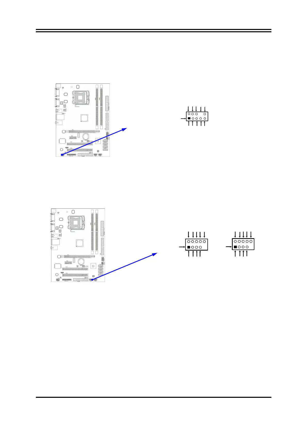
(1) Line-Out/MIC Header for Front Panel (9-pin): AUDIO
This header is connected to Front Panel Line-out, MIC connector with cable.
(2) USB Port Headers (9-pin) : USB2 / USB3
These headers are used for connecting the additional USB port plug. By
attaching an option USB cable, your can be provided with two additional USB
plugs affixed to the back panel.
(3) Speaker connector: SPEAK
This 4-pin connector connects to the case-mounted speaker. See the figure
below.
(4) Power LED: PWR LED
The Power LED is light on while the system power is on. Connect the Power
LED from the system case to this pin.
(5) IDE Activity LED: HD LED
This connector connects to the hard disk activity indicator light on the case.
USB Port Headers
Pin 1
USB2
VCC
-DAT
GN
+DATA
VCC
OC
-DAT
GND
+DATA
Pin 1
USB3
VCC
-DAT
GND
+DATA
VCC
OC
-DAT
GND
+DATA
Line-Out, MIC Headers
AUDIO
Pin 1
Lineout2-L
Lineout2-R
Sense-FB
Audio-GND
LINE2-JD
Audio-JD
2
9
10
KEY
MIC2-L
MIC2-JD
MIC2-R