14
2-2-3 Header Pin Definition
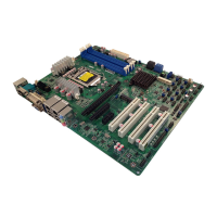
(1) Line-Out/MIC Header for Front Panel (9-pin): FP_AUDIO
This header is connected to Front Panel Line-out, MIC connector with cable.
Line-Out, MIC Headers
Pin 1
Lineout2-L
Lineout2-R
Sense-FB
Audio-GND
LINE2-JD
Audio-JD
2
9
10
KEY
MIC2-L
MIC2-JD
MIC2-R
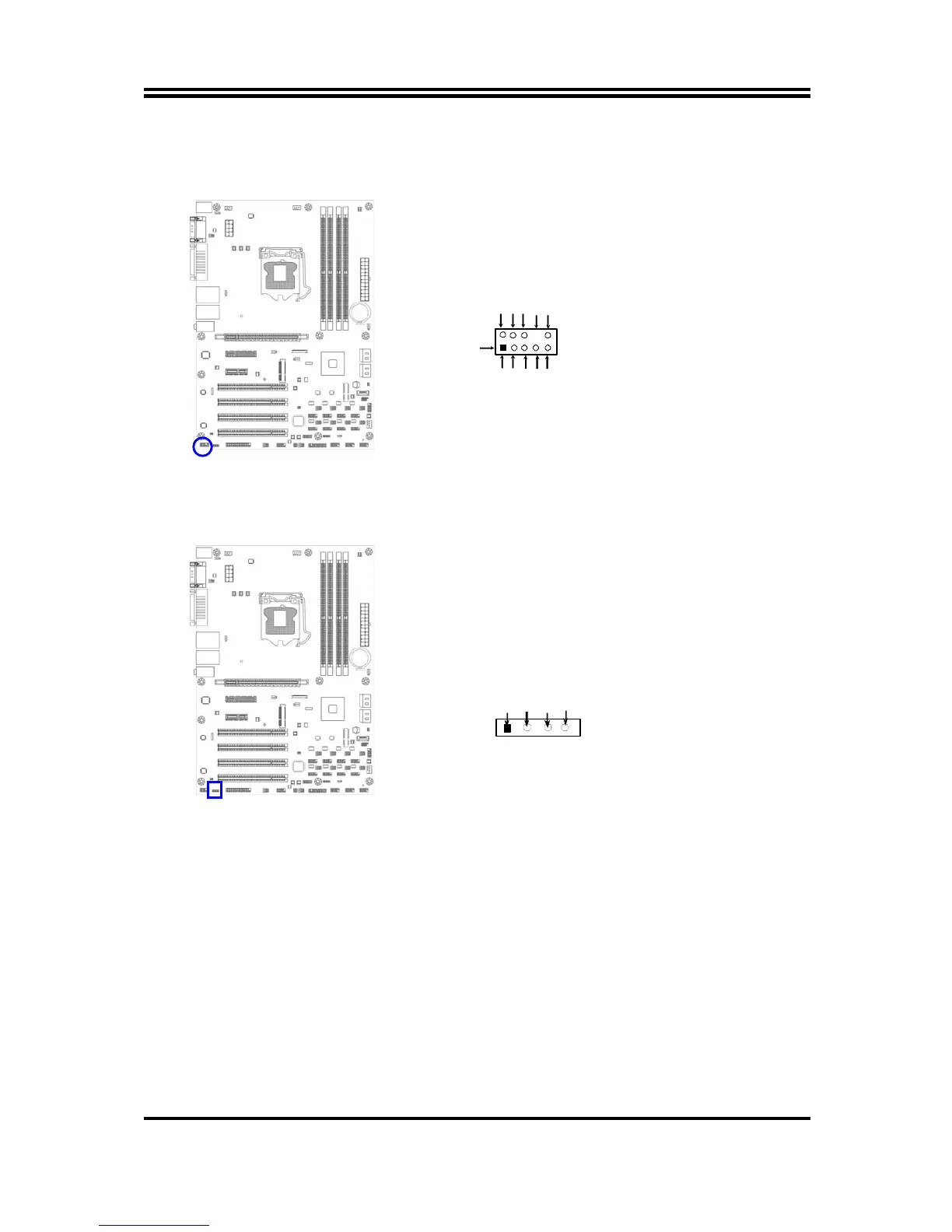
(2) CD AUDIO-In Headers (4-pin): CDIN
CDIN are the connectors for CD-Audio Input signal. Please connect it to
CD-ROM CD-Audio output connector.
CD Audio-In Headers
CDIN
1 4
GNDCD-L
CD-RGND
3) Speaker connector: SPEAK
This 4-pin header connects to the case-mounted speaker. See the figure below.
(4) Power LED: PWR LED
The Power LED header is light on while the system power is on. Connect the
Power LED header from the system case to this pin.