Intel® RAID Controller RS25DB080 Hardware User’s Guide 13
3 Intel
®
RAID Controller RS25DB080
Characteristics
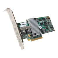
Figure 4. Card Layout
The Cache Memory Board component is a printed circuit board with RAID controller
cache memory chips on it that mounts directly to the base controller through the Memory
Board Connector J2 and is secured by one screw. It provides a 20-pin connector for
remote battery backup module or SuperCap module installation support for base
controllers that do not have a 20-pin connector on the controller.
Figure 5. Cache Memory Board
J2B1
J5B1 J5A1
J6A1
J2B2
J2B3 J2B4
J1A7
J1A5
J1A4
J1A2J1A1 J1A3
AF003891

 Loading...


