- 99 -
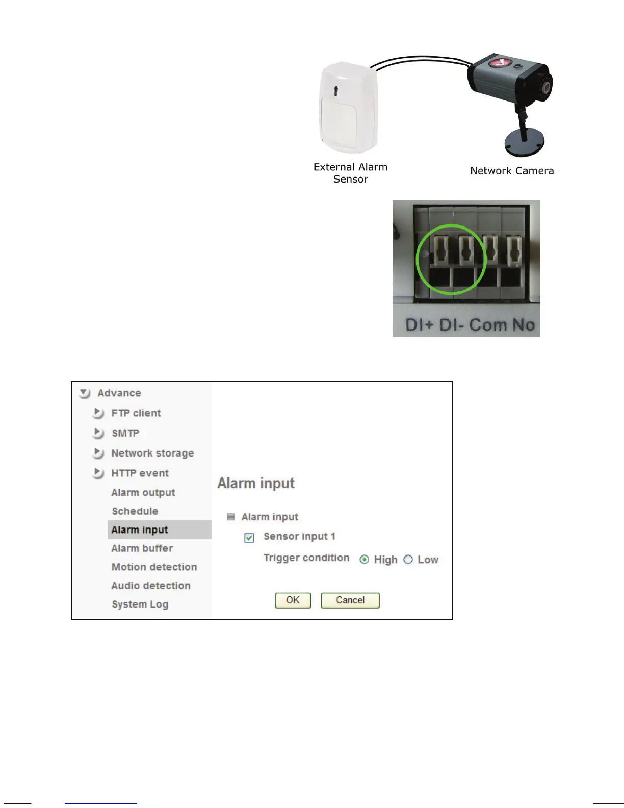
Camera -> Advance -> Alarm Input:
If your Network Camera features a
terminal block connector (digital I/O)
for the connection of external alarm
sensors, you can set up the trigger
condition for the input on this page.
There are two types of sensors when
it comes to the actual alarm trigger.
One opens the electric circuit in case
of an alarm (digital I/O = low); the
other closes the electric circuit (digital I/O = high).
The camera allows defining of the default state of
the sensor and the alert state.
Digital I/O terminal block connector showing pins
1 and 2 (circled) for the connection of an external
sensor.
Sensor input 1: Select the input sensor from the list. INTELLINET NETWORK
SOLUTIONS network cameras feature only one sensor.
Trigger condition: This value describes the alarm state of the sensor. The
correct value depends on the sensor.