EasyManua.ls Logo

IntelliSense DT-7435 EU DUAL TEC User Manual

Default Icon
2 pages
To Next Page IconTo Next Page
Page #1 background imageLoading...
Page #1 background image
TBL TBL T T NO EOLCV-NC V+
132
TEST
50%
100%
75%
25%
Select the mounting location.
¹ Wire the unit.
¸ Mount the unit.
ºa Walk-test the sensor.
Mounting Location Guidelines
2.3 m mounting height
Avoid direct or reflected sunlight
Aim sensor away from windows or heating/
cooling devices
Sensor must have a clear line-of-sight to
protected area
See Special Instructions for pet applications
Use a small screwdriver to unfasten the housing
latch. Gently pull apart the housings.
Push outward on the PCB latch and lift the PCB
out of the housing.
Slide the wire through the wire channel and wire
access in the back housing.
Mount the back housing flat against a wall or in a
corner.
Replace the PCB.
Connect wires as shown using 0.3 - 1.0 mm
2
wire size. Observe proper polarity.
Apply power to the unit. Initialization is complete
when the LED stops flashing slowly.
Adjust the microwave range to minimum setting
(25%) by turning the range adjustment counterclock-
wise using a small screwdriver.
Replace the front housing.
Begin walking through the detection area.
- The LED will turn red, indicating an alarm detection.
Increase the microwave range as necessary.
Repeat the items in step 5a until proper detection
range is obtained.
ºb Optional: Walk-test using Zone Finder.
Use a screwdriver to short the test pads.
During the Zone Finder walk-test mode, the LED
turns:
- green for PIR detection;
- yellow for microwave detection.
Adjust the microwave range as necessary.
Zone finder mode times out after ten minutes.
Corner
Mount
Wire Channel
Wall Mount
75%
100%
25%
50%
DT-7435 EU DUAL TEC
®
Motion Sensor Installation Instructions
Use the Zone Finder mode to identify the PIR and/
or microwave pattern. In Zone Finder mode the red
LED is disabled.
· Separate the sensor housings and
remove the printed circuit board (PCB).
DT-7435
Remove look-down
mask for non-pet
applications
Question and Answer IconNeed help?

Do you have a question about the IntelliSense DT-7435 EU DUAL TEC and is the answer not in the manual?

IntelliSense DT-7435 EU DUAL TEC Specifications

General IconGeneral
Coverage Angle90°
ModelDT-7435 EU
CategoryAccessories
TypeMotion Detector
TechnologyPIR + Microwave
Housing MaterialPlastic

Summary

Motion Sensor Installation Steps

Select Mounting Location

Guides on choosing an optimal location for motion sensor placement, considering height and environmental factors.

Separate Sensor Housings and Remove PCB

Instructions for opening the sensor housing and safely removing the printed circuit board for wiring.

Mount the Unit and Wire Connections

Steps for securing the sensor's housing and connecting the wires, including polarity and wire gauge.

Walk-Test the Sensor

Procedures for testing the sensor's detection range and sensitivity using LED indicators and range adjustments.

Motion Sensor Product Information

LED Indicators and Operation

Describes the function and meaning of different LED colors and patterns during sensor operation and testing.

DIP Switch Settings

Details the function of DIP switches for configuring sensor sensitivity and LED behavior.

Trouble Shooting Common Issues

Provides solutions for common sensor problems, such as rapid red LED flashing, indicating supervision or self-test failures.

Pet Immunity Installation Guidelines

Special mounting and placement instructions to ensure optimal pet immunity for the motion sensor.

Detection Patterns and Specifications

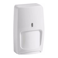
Illustrates sensor coverage and lists key technical specifications including range, power, temperature, and dimensions.

Related product manuals