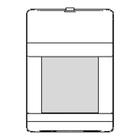
Figure 4 Changing the Lens
WIRING
Terminals TB1 and TB2 (MC-550T only) are located at the top edge of
the PCB. Wire the MC-550 / MC-550T as shown in Figure 3 using 14-
22 AWG wire. After the wiring is complete, push as much of the wire
as possible back into the wall.
®
For proper wiring methods, refer to the National Electrical Code, NFPA 70.
To install the optional pet-alley lens*:
• Remove the front cover of the
MC-550 / MC-550T. (See Fig-
ure 1.)
• Press up on the Bug Guard
latch and then pull the Bug
Guard out of the front cover
.
• Remove the existing lens, and
place the new lens in with the
SMOOTH side facing outward.
• Install the lens with the small
slot at the top and the large
slot at the bottom.
CHANGING THE FRESNEL LENS
Figure 5 Printed Circuit Board
TB1
+1
0
Self Test
High
Normal
K1
Low
No jumper
NCC
TB2
S1
TMPR
LED
Enable
J3
J1
ALIGNMENT NOTCH
DS1 (Alarm LED) illuminates
when an alarm condition is
triggered.
Jumper position J1 on the PCB
is used to set the sensitivity of
the PIR detector.
Using the chart below, configure
the MC-550 / MC-550T for the
sensitivity best suited to your
application.
Normal (PC3) Jumper center & bottom pins
High (PC2)
Jumper top & center pins
Low (PC4)
Parked on one pin or off
A sensitivity setting of low is not recommended when run-through perfor-
mance is required.
Note: Do not mount the unit at 10 feet / 3 m when using the low
sensitivity setting.
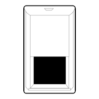
LOOK-DOWN WINDOW
SMALL SLOT
LARGE SLOT
BUG
GUARD
BUG GUARD
LATCH
ALIGNMENT NOTCH
Important: Align with appropriate
notch on the PCB (refer to Range
Chart on the next page).
-1
Install jumper at J3 to enable
Alarm LED (DS1).
Jumper is
factory installed.
(MC-550T Only)
SENSITIVITY JUMPER J1
Figure 3
Wiring
TAMPER
24 VDC
25mA
(MC-550T Only)
POWER
12 VDC
20mA
ALARM
24 VDC
100mA
TB2 TB1
• Install the look-down mask (optional) over the inside
of the look-down window.
• Place the Bug Guard into the look-down window then snap the Bug
Guard back into place.
• Reassemble the housing.
PIR SENSITIVITY
Important: When using pet-alley lens, optimum mounting height is 4
feet / 1.2 m and adjust PCB to +1 position.
*Lens Option Kit Part Number 0-000-012-01
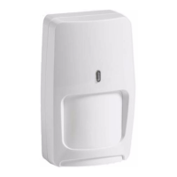
Microcontroller Based
Passive Infrared
Motion Sensor
Range: 50' x 40'
15 m x 12 m
INSTALLATION INSTRUCTIONS
Models
MC-550
MC-550T
LATCH
PCB
LATCH
LATCH
RELEASE
SLOT
WIRE
ENTRY
KNOCK-
OUTS
Figure 2 Rear Housing
LATCH
RELEASE
SLOT
Figure 1 Opening the
MC-550/
MC-550T
ALIGN WITH
NOTCH IN PCB
FOR CORNER
MOUNTING
FOR
OPTIONAL
SWIVEL
MOUNT
BRACKET
• 50' x 40' / 15 m x 12 m range
• Dual element PIR
• Dense detection pattern
• Wide angle optics
• Low 20 mA current draw at
12 VDC
• 10-14 VDC operation
• Zone finder
• Energized form A alarm relay
FEATURES
• Microcontroller signal
processing
• Temperature compensation
• Diagnostics
• RF and white light immunity
• Selectable PIR sensitivity
• Mounting flexibility: on walls or
in corners
• Bug proof
The MC-550 / MC-550T is designed for use indoors. Make sure the
sensor has a clear line-of-sight to the protected area. Infrared energy
cannot penetrate solid objects. If the sensor is blocked, it will not
alarm.
Aim the sensor toward the interior of the room, away from windows
and heating/cooling sources. The unit can be corner or wall mounted
at either 4' / 1.2 m, 7'6" / 2.3 m, or 10' / 3 m (see Range Chart on
the next page).
MOUNTING LOCATION
False alarm immunity from small animals with the MC-550/550T can
be expected in installations with:
Any number of cats (or similar sized animals)*
Any number of birds, confined to a cage
Birds flying randomly though a warehouse setting
Any number of rats*
*The total weight of animals cannot exceed 15 pounds / 7 Kg.
For false alarm immunity with the above mentioned animals the
following installation procedures must be observed:
• Use the standard wide angle lens optics
• Mount the sensor at 7'6" or 10' / 2.3 or 3 m
• Set the PIR pulse count at normal (PC3) or low (PC4)
• Make sure no animal(s) can get within 6' / 1.9 m in the sensor's
direct line-of-sight.
MOUNTING PROCEDURE
Prepare the sensor for mounting
by removing the front cover and
printed circuit board (PCB).
To remove the front cover of
the sensor, use a screwdriver
to slide into the latch release
slot located at the top of the
unit and then gently push up.
(See Figure 1.)
To remove the PCB, press
the latch holding the PCB in
place and gently pull up on
the PCB until it releases.
(See Figure 2.)
Using the rear housing
as a template, mark
mounting and wire access
locations. Pull several
inches of wire into the
housing and fasten the
rear housing to the wall.
(Pulse count 2)
(Pulse count 3)
(Pulse count 4)