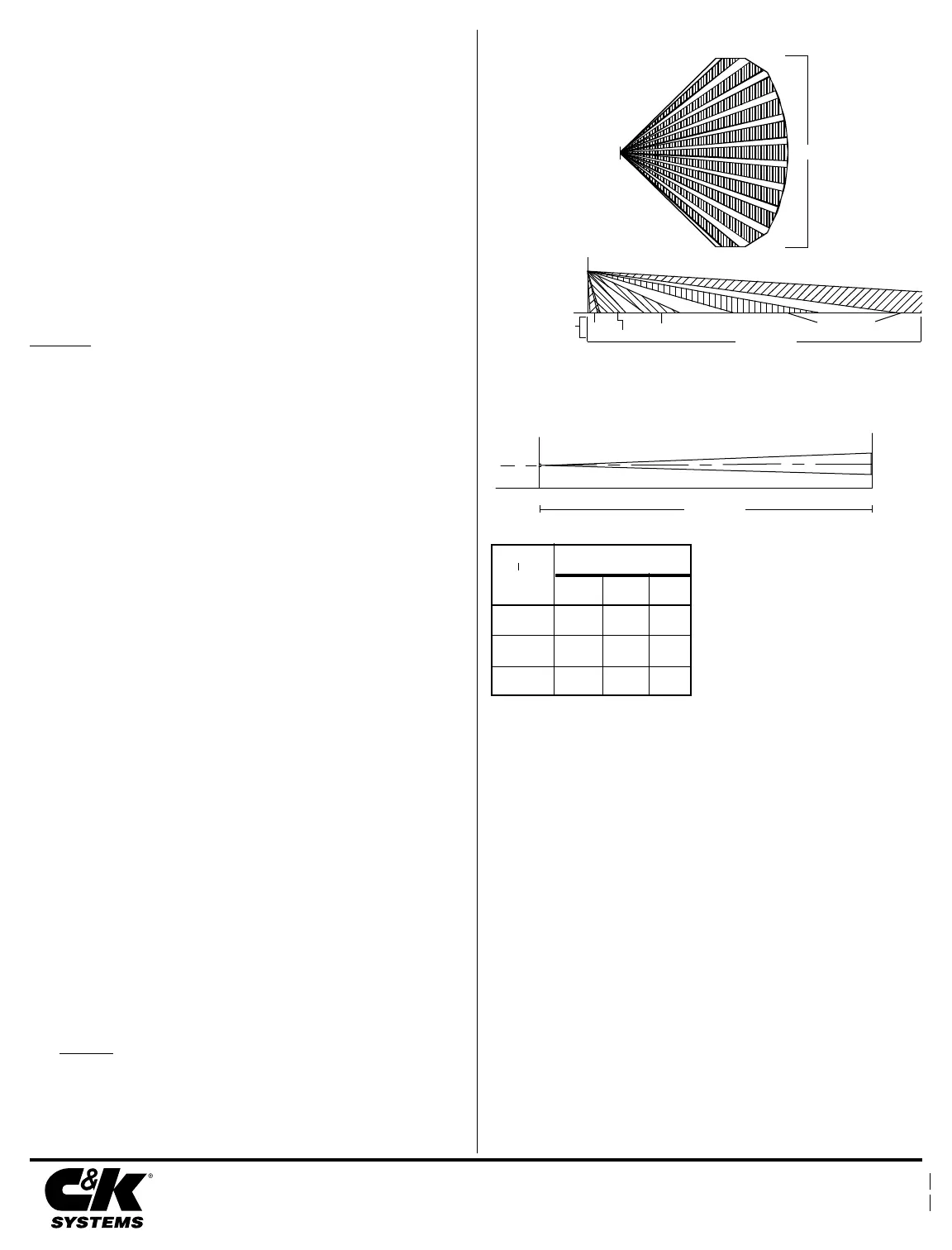
PROTECTION PATTERNS
TOP VIEW
Wide Angle Lens
40' / 12 m
7'6"
2.3 m
Long Range
ZONES
Down
Lower
Intermediate
floor
SIDE VIEW
Wide Angle Lens
TOP VIEW
Pet-Alley Lens
The TOP VIEW Pet-Alley lens is the same
as the TOP VIEW Wide Angle lens.
SIDE VIEW
Pet-Alley Lens
4'
1.2 m
MTG
HEIGHT
+1 0 -1
PCB POSITION
50' N/A N/A
N/A 50' N/A
N/A N/A 50'
MC-550 / MC-550T RANGE CHART
50' / 15 m
Ongoing self-test occurs every twenty-four hours. If a self-test fails, it retests
every five minutes. Ongoing self-test does not flash the LED unless there is a
failure. Power up and user initiated self- tests both perform the same functions.
To perform a user initiated self-test, short the two self-test pads (refer to
Figure 5).
The LED flashes once per second during the power up and user initiated
self- test. If the unit fails any self-test, it will continue to flash the LED once
per second.
SELF-TEST
To disable the alarm LED (DS1) after walk-testing the sensor, remove the
jumper from position J3 on the PCB. See Figure 5.
ALARM LED DISABLE (MC-550T Only)
Range:
50' x 40'
15 m x 12 m
Power requirements:
10 - 14 VDC
20 mA, 12 VDC
3V peak to peak at
nominal 12VDC
Alarm relay:
Form A (normally-closed)
100 mA, 24 VDC
Tamper switch:
(MC-550T Only)
Form A (normally closed)
25mA, 24 VDC
RF immunity:
30 V/m
10 MHz - 1000 MHz
PIR white light immunity:
6,500 Lux
PIR sensitivity:
jumper selectable
(high, normal & low)
PIR fields of view:
dual element
22 long range
6 intermediate
3 lower
2 look-down
Operating temperature:
32
o
to 120
o
F / 0
o
to 49
o
C
Relative humidity:
5% to 95% non-condensing
Dimensions:
3-1/2" H x 2-1/2" W x 1-13/16" D
9.0 cm x 4.4 cm x 4.5 cm
Weight:
3.0 oz / 85.27 g
Packaged product is 4.5 oz / 127.9 g
Approvals/listings:
FCC/IC verified
CE approved
UL listed
SPECIFICATIONS
C&K is a registered trademark of C&K Components, Inc.
IntelliSense is a registered trademark of C&K Systems, Inc.
All rights reserved.
© 1996 C&K Systems, Inc.
5-051-431-00 Rev D
Important: For UL certificated installation, the MC-550 / MC-550T
must be connected to a UL listed power supply or UL listed control
unit capable of providing a minimum of four hours of standby
power.
This device has been tested to compliance with the EMC Directive
89/336/EEC for Residential, Commercial and Light Industry
applications, according to standards EN50081-1 and EN50082-1.
IC Notice:
This Class B digital apparatus meets all requirements of the Canadian Interference-
Causing Equipment Regulations.
Cet appareil numérique de la Classe B respecte toutes les exigences du Règlement sur le matériel
brouilleur du Canada.
FCC Notice: This equipment has been tested and found to comply with the limits for a Class B digital device,
pursuant to part 15 of the FCC Rules. These limits are designed to provide reasonable protection against harmful
interference in a residential installation. This equipment generates, uses and can radiate radio frequency energy and, if
not installed and used in accordance with the instructions, may cause harmful interference to radio communications.
However, there is no guarantee that interference will not occur in a particular installation. If this equipment does cause
harmful interference to radio or television reception, which can be determined by turning the equipment off and on, the
user is encouraged to try to correct the interference by one or more of the following measures: 1) Reorient or relocate the
receiving antenna, 2) Increase the separation between the equipment and receiver, 3) Connect the equipment into an
outlet on a circuit different from that to which the receiver is connected. The installer can also consult an experienced
radio/television technician for additional suggestions, if necessary.
WALK-TEST
Apply power to the unit. The power up self-test takes 3.7 minutes. The LED
flashes during power up self-test. Begin walk-testing when the alarm LED
(DS1) goes out. (The unit is in the zone finder mode for the first 10 minutes.)
Walk across the protected area at the ranges to be covered. Two to four normal
steps across the pattern should make the alarm LED light. Wait for the alarm
LED to go out, then continue walk-testing. When there is no motion in the
protected area, the alarm LED should be off.
ZONE FINDER
The sensor will enter a 10 minute zone finder mode after a successful power
up diagnostics test or a user initiated test. Either one of these tests takes
approximately 3.7 minutes.
While in the zone finder mode, the installer can determine the precise protec-
tion pattern by further walk-testing the unit. The alarm LED will activate
every time a zone edge is crossed.
Important: The MC-550 / MC-550T should be tested at least once each
year to ensure proper operation.
The information in this manual has been revised. For
your convenience, dashed lines were added in the
margins to help you locate the changes. The changes
consist only of additions or revisions, deleted
information is not marked.
http://www.cksys.com
4' / 1.2 m
7'6" / 2.3 m
10' / 3 m
50' / 15 m
50' / 15 m
(EMC Directive: Residential,
Commercial and Light Industrial)
 Loading...