Do you have a question about the Interface 9840 and is the answer not in the manual?
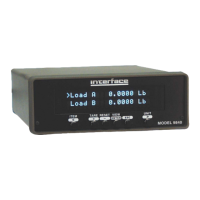
Description of the "Item" button's function for cycling through displayed items.
Description of the "Tare" button's function to zero load or torque readings.
Explanation of the "Reset" button's function to reset peak, valley, or position values.
Function of the "View" button to switch between two virtual displays.
Function of the "Esc" button to freeze/unfreeze the display or exit menus.
Function of the "Print" button to output data or freeze the display.
Function of the "Unit" button to cycle through available units for displayed items.
Allows setting common math options like base area for PSI/MPa or base length for position.
Configures the source and scaling for the standard analog output signal.
Enables manual selection of load or torque cell calibration data from stored lists.
Procedure for removing stored calibration data for a specific cell from the unit's memory.
Access to all methods of calibrating the Model 9840, including checks and various calibration types.
Setup for the 4 contact closure limit switches, including source, units, and set points.
Configuration of system-wide parameters like printer baud rate, auto-identify, and communication settings.
Customization of front panel display settings, including filters, decimal digits, and second line content.
Description of the 4 opto-isolated digital inputs and their standard functions for control.
Instructions for installing the USB driver to enable PC communication with the unit.
Fetches the model, version, and serial number of the unit.
Returns a list of available item and unit numbers for use with other commands.
Commands to view or set user data like base area and base length for calculations.
Commands to view or set the analog output source and scaling parameters.
Commands to view, select, or delete calibration data for connected sensors.
Commands to perform various calibration procedures, including checks and point calibrations.
Commands to view or set the 4 contact closure limit switches and their conditions.
Commands to view or set system-wide parameters like baud rate and communication settings.
Commands to configure display settings such as filters, decimal digits, and second line content.
| Brand | Interface |
|---|---|
| Model | 9840 |
| Category | Measuring Instruments |
| Language | English |