Do you have a question about the Interface GOLD STANDARD and is the answer not in the manual?
Software and Configuration Manual for the Load Calibration Frame, 15-330 Rev. A.
Details software, hardware, and computer equipment warranties, remedies, and liability limitations.
Guidelines for safe operation, identifying hazards, and understanding system functions.
Covers emergency stops, interlocks, piston safety, and sudden movement dangers.
Addresses load cell overload, control adjustments, feedback loss, and valve silting.
Discusses risks of power failures and safety for servicing hydraulic power supply.
Details LVDT, sensors, amplifiers, adapters, and control buttons.
Checklist for uncrating, positioning, and electrical setup of the load frame.
Procedure for installing adapters and configuring the test setup.
Describes WGoldCfg, WCalGold, WCGold, menu commands, and button bar functions.
Detailed steps for performing a calibration, including data entry and offset determination.
Step-by-step guide for conducting a creep test and recording results.
Covers performance analysis, shunt calibration, and data reporting options.
Configuration of program paths and Analog-to-Digital converter settings.
Details on calibration set point screen buttons and field entries.
Identification and function of various components in the hydraulic power unit.
Procedures for filter maintenance, accumulator charging, and oil replacement.
Schematic illustrating the functional connections of system components.
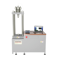
Details on features, standard configuration, and technical specifications.
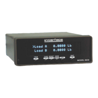
Overview of features, benefits, and detailed specifications for the indicator.
Details on signal conditioner features, specs, dimensions, and wiring diagrams.
Wiring diagram for the 12802 cable, showing load cell and instrument connections.
Outline drawing with dimensions and models of the load frames.
Electrical schematic for the hydraulic power unit.
Wiring schematic for the project box used with the load calibration frame.
Technical drawing for the THD-ADAPT-KIT-1 calibration adapters.
Information about Interface Inc., its history, and its client base.
| Brand | Interface |
|---|---|
| Model | GOLD STANDARD |
| Category | Measuring Instruments |
| Language | English |