7418 East Helm Drive • Scosdale, Arizona 85260 • 480.948.5555 • www.interfaceforce.com
Page 14 of 45
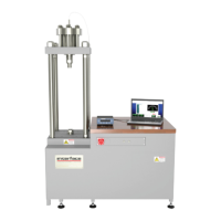
One 208-240 VAC, 30 amp, single phase circuit is needed for the hydraulic power supply. The plug
supplied with the system is NEMA 6-20.
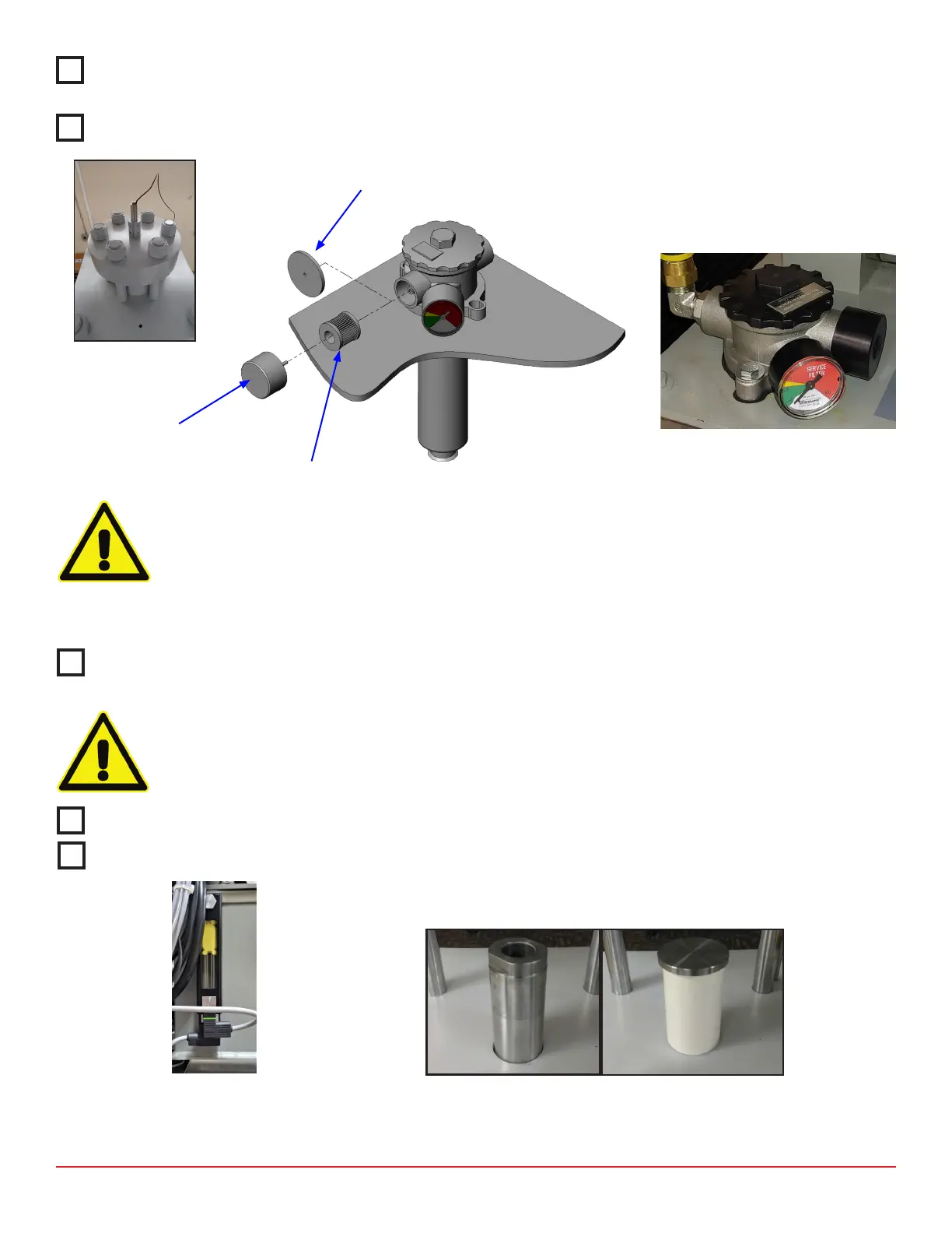
Install the LVDT posion sensor on top of the load cap using (2) cap screws (see Figure 3).
CAUTION
Do not change the locaon of the LVDT in the bracket.
The shipping gasket must be removed and replaced with the breather lter before operang system.
The gasket can be accessed by removing the breather cover on lter housing (Figure 4).
CAUTION
Failure to replace shipping gasket could result in excess pressure or vacuum inside the tank and
damage to the pump.
Check the system oil level (Figure 5).
Remove the piston retainer if installed (Figure 6).
(Piston) (Piston Retainer)
NOTE: Shipping gasket must
be removed before pung
hydraulic unit into service.
Shipping gasket Installaon Remove breather
lter for shipping and insert shipping gasket
between breather cover and lter housing.
Breather Filter
Breather Cover