7418 East Helm Drive • Scosdale, Arizona 85260 • 480.948.5555 • www.interfaceforce.com
Page 31 of 45
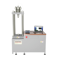
The HPS (Hydraulic Power Supply) unit has three levels of ltraon. The sucon strainer is located inside
the reservoir and should be cleaned and replaced every me the tank is drained for any reason. The
strainer is made of non-rusng Stainless steel wire mesh and may be re-cleaned with solvent for reuse if
desired.
The high pressure lter and return medium pressure lter elements must be thrown away and replaced
with new ones. Both of these last two lters are equipped with “Element-condion” indicators. When
the indicator reaches the red zone the element should be replaced. This is with the power unit running
at maximum ow; NOT when unloaded. The cycle rate or speed of operaon needs to be at maximum
to read the lter’s condion. When changing out the lters, make sure that the HPS pressure has been
reduced to zero.
The hydraulic power supply uses the following lters:
Return Filter: KRW-RT20-G10B (KR West)
High Pressure Filter: SF-014-H-10-B-T-UIZ-0-V (Stau)
Your hydraulic power supply is equipped with a bladder style hydraulic accumulator to damp out shocks
and to minimize pressure spikes and sags. The accumulator has been pre-charged with nitrogen gas
to a pressure of 2100 – 2400 psi and will funcon properly at start-up. No addional adjustments are
necessary.
The hydraulic power supply is pre-lled with high quality/premium an-wear, an-foam hydraulic oil like
Chevron Rando (ISO 32) or equivalent. This oil should be checked every 500 hours of usage. At these 500
hour intervals, there are visual observaons and test that can be conducted to determine if the hydraulic
oil is sll useable or if it should be changed.
• Water ingress – if the hydraulic oil has a milky appearance, then water may have been introduced into
the hydraulic circuit or reservoir. Try to determine the source of the water ingress and eliminate it,
then replace the oil.
• Heat – Replace the oil if the color has become darker or if it has a burnt odor.
• Contaminaon – Fluid analysis can be conducted on an oil sample to see if the parcle contaminaon
level has increased beyond acceptable limits. If so, replace the oil and lter elements.
• Oxidave Degradaon & Addive Depleon – Fluid analysis can determine if these condions have
started to occur. If so, replace the oil and lter elements.
When it is me to replace the hydraulic oil, it is best to start by using a hydraulic transfer pump. To do this,
remove the lter cap assembly and insert the sucon line of the pump and remove as much oil as possible.
The residual oil can then be drained through the drain plug. Make visual observaons inside of the
reservoir to see if there is any residue on the boom. If residue is present, ush out with a small volume of
oil and discard.
Replace the drain plug and rell the reservoir with equivalent ISO 32 hydraulic oil using the lter assembly
port. About 10 gallons will be required to ll the reservoir and actuator. It will be necessary to cycle the
piston actuator up and down at least 5 mes to remove air from the hydraulic lines and ll the actuator.
Top o the oil level in the reservoir and then replace the lter element. The hydraulic system is now ready
for use.