7418 East Helm Drive • Scosdale, Arizona 85260 • 480.948.5555 • www.interfaceforce.com
Page 15 of 45
CAUTION
Do not complete the threaded adapter string unl the system has been tested to ensure the
LVDT will control the piston height. This can be done by turning the pump on when the load
frame is empty and manually liing the swivel adapter. The piston should retract to the lowest
posion.
1. Read the “Operating Safety Procedures”.
2. Install the Standard load cell on the piston.
3. If the Standard load cell does not have an integral Control Load Cell bridge, install a Control Load Cell on
the Standard load cell. Control Load Cell bridge may be part of the 1600 or 1800 series load cell or may be
a separate load cell. The Control Load Cell bridge must be trimmed to 2 mV/V for proper control. Any
Load Cell trimmed to 4 mV/V and with twice the capacity of the Load Cell Standard may be used as a
Control Load Cell. For example: a 50 klbf Load Cell trimmed to 4 mV/V may be used to control the frame
with a 25 klbf Load Cell Standard. The goal is to have a 2 mV/V control signal at the rated load.
4. Install the DUT load cell using a standard or custom threaded adapter. Custom adapters are available from
Interface Inc.
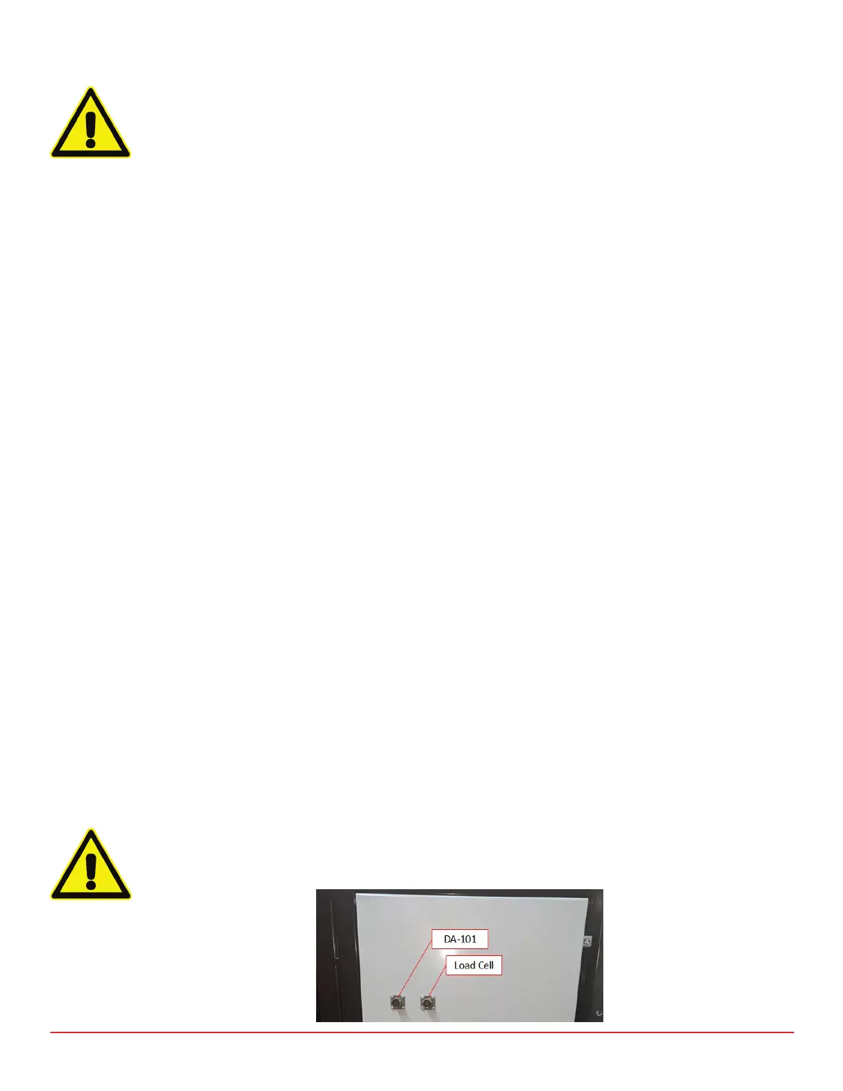
5. Attach the Control Load Cell cable (15700) from the Control Cell Bridge to the connector shown as “Control
Load Cell” on the back of the load frame (see Figures 7 and 10). Do not disconnect this cable while the
hydraulic pump is running or damage may occur.
6. Attach the DA-101-USB cable (15936) from the “Set Point Command” connector on the back of the load
frame to the DA-101-USB Analog Output connector (see Figures 7 and 10).
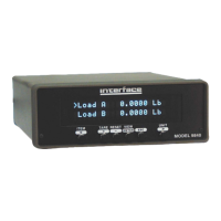
7. Attach the Reference Standard cable (CT-177) to the Load A connector on the 9840 indicator. Attach the
Device Under Test (DUT) cable (CT-338) to the Load B connector on the 9840 indicator (See Figure 9).
Please consult Interface Inc. if the connection on your cable does not match your load cell. In most cases,
Interface Inc. can supply you with the one you need. Attach the 208/240 VAC 1 PH system power using the
supplied mating connector (see Figure 7).
8. Set up the computer. The computer and monitor may be plugged into the power outlet on the back of the
load frame (see Figure 7). Connect DA-101-USB power cord to DA-101-USB power input connector and AC
outlet. Connect the USB cable from DA-101-USB to computer. Turn on the pump at the Start/Stop switch.
As the piston raises, carefully raise the slack adapter swivel stem by hand to the top position. The piston
should immediately begin to lower. If not, the control cables to the Control Load Cell or the LVDT must be
checked for proper connection.
CAUTION
Do not aempt to complete the threaded adapter string unl the LVDT control is working
properly.