T8 Torque Sensor Operation Manual
Interface Inc. ● 7401 East Butherus Drive, Scottsdale, Arizona 85260 USA ● Phone 480.948.5555 ● Fax 480.948.1924
www.interfaceforce.com ● Email: contact@interfaceforce.com ● 800.947.5598
Page 10 of 11
7
Maintenance
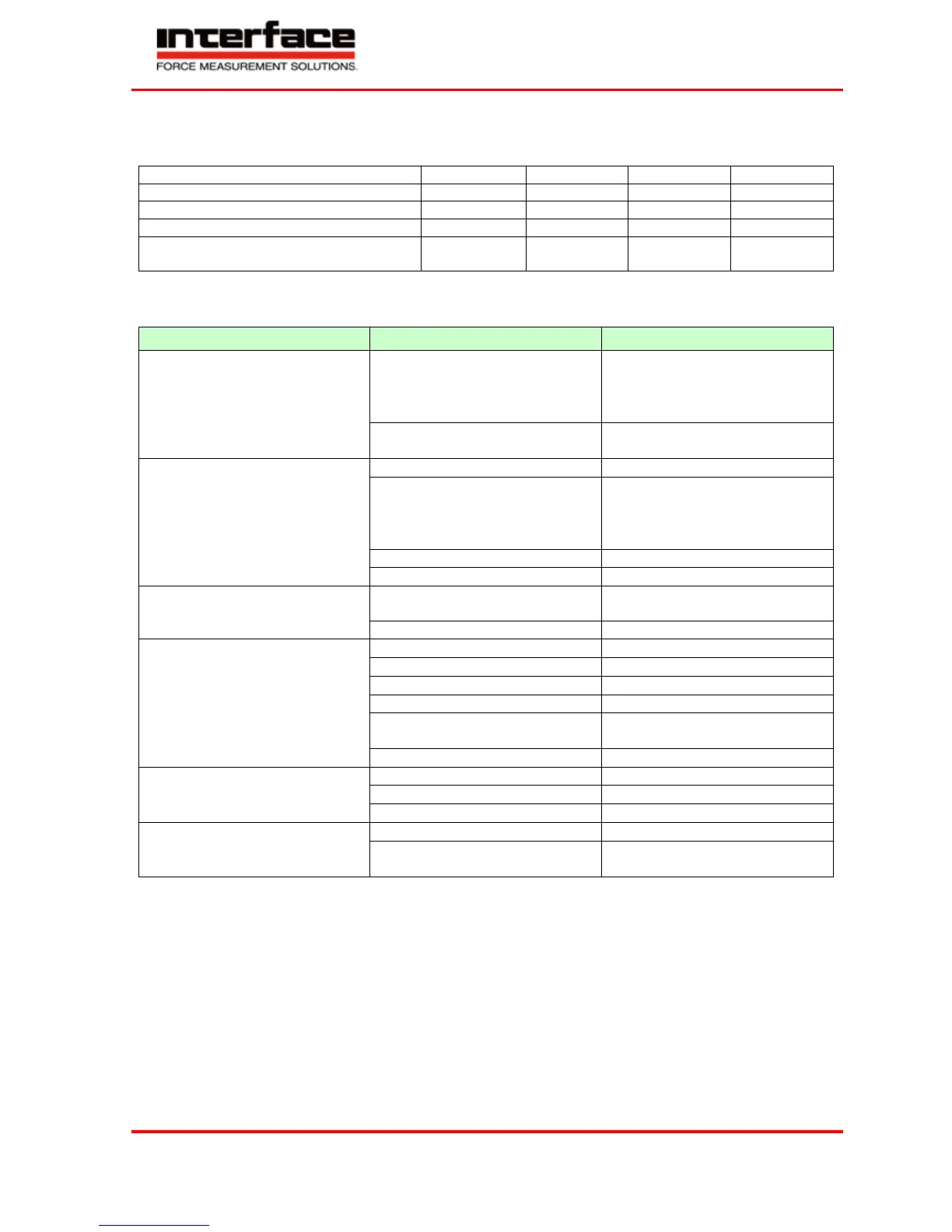
Maintenance Schedule
Control of cables and connectors
Control of fixation (flanges, shafts)
Have bearings exchanged by Interface
Trouble Shooting
This chart is used for searching for the most frequent errors and their elimination
Problem Possible Cause Trouble Shooting
• Outside of permissible range
• Connect excitation
• Cable defect
• No mains supply
Signal output connected wrong
• Connect output correctly
• Evaluation electronics defect
Sensor does not react to torque
• Outside of permissible range
• Connect supply
• Cable defect
• No mains supply
Connector connected wrong
Axial position rotor to stator
outside of tolerance
Zero point outside of tolerance
• Release from distortion
• Check evenness of flange-
surfaces
Alignment of shaft not correct
• Balance the corresponding
parts
8
Decommission
All sensors must be dismantled professionally. Do not strike sensor housings with tools. Do not apply bending
moments on the sensor, e.g. through levers. The torque sensor must be supported to avoid falling down during the
dismantling.
9
Transportation and Storage
The transportation of the sensors must occur in suitable packing.
For smaller sensors, stable cartons which are well padded are sufficient (e.g., air cushion film, epoxy crisps, paper
shavings). The sensor should be tidily packed into film so that no packing material can reach into the sensor (ball
bearings). Larger sensors should be packed in cases.