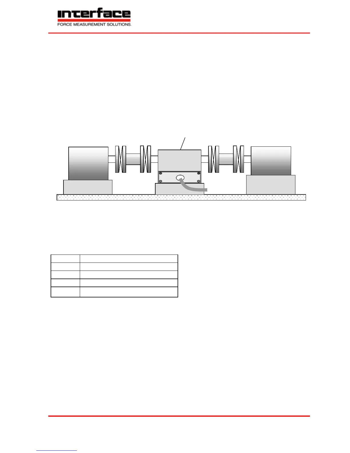
Foot Version Assembly
The sensor can be installed as a bearing block. A double-jointed coupling must be mounted on each shaft end. By
this, inevitable axis offsets, which can also appear during the period of operation, are being balanced. If no
couplings are used, very large transverse forces can occur in the bearings of the sensor as well as in the bearings on
drive and output which will limit their life span very strongly. Further, large bending moments will emerge in the
shaft.
At small torques (< 20 N·m) connect the sensor electrically and observe the signal; the measurement signal
may not exceed the limit values...
Shafts must be cleaned with solvent (e.g. acetone) before the assembly. No foreign particles may adhere to them.
Shift couplings on shafts (use entire clamping length of the coupling) and align shafts. Absolutely assure that the
data of the couplings (axis offset, angular offset, tension, compression) are not exceeded.
Torque sensor
5
Electrical Connection
Pin Connection
Also see test certificate.
The firmly connected cable has free ends
Green Excitation GND 0 V
Brown Excitation + 12 ... 28 VDC
Yellow Signal ±5 V / (±10 V)
White Signal GND 0 V
Netting Shield
Cable
Only use a shielded cable with preferably small capacity. We recommend measuring cables from our product
range. They have been tested in combination with our sensors and meet the metrological requirements.
Shielding Connection
In combination with the sensor and the external electronics, the shield forms a Faraday Cage. By this, electro-
magnetic disturbances do not have any influence on the measurement signal.
Running of Measuring Cables
Do not run measuring cables together with control or heavy-current cables. Always assure that a large distance is
kept to engines, transformers and contactors, because their stray fields can lead to interferences of the measuring
signals.
If troubles occur through the measuring cable, we recommend to run the cable in a grounded steel conduit.