T8 Torque Sensor Operation Manual
Interface Inc. ● 7401 East Butherus Drive, Scottsdale, Arizona 85260 USA ● Phone 480.948.5555 ● Fax 480.948.1924
www.interfaceforce.com ● Email: contact@interfaceforce.com ● 800.947.5598
Page 9 of 11
6
Measuring
Engaging
The warming-up period of the torque sensor is approx. 5 min. Afterwards the measurement can be started.
The warming-up period of the torque sensor is approx. 5 min.
Direction of Torque
Torque means clockwise or clockwise torque if the torque acts clockwise when facing the shaft end. In this case a
positive electrical signal is obtained at the output.
Torque sensors by Interface can measure both, clockwise and counter-clockwise direction.
Static / Quasi-Static Torques
Static and/or quasi-static torque is a slowly changing torque.
The calibration of the sensors occurs statically on a calibration device. The
applied torque may accept any value up to the nominal torque.
Dynamic Torques
General
The static calibration procedure of torque sensors is also valid for dynamic applications.
Note: The frequency of torques must be smaller than the natural frequency of the mechanical
measurement setup.
The band width of alternating torque must be limited to 70 % of the nominal torque.
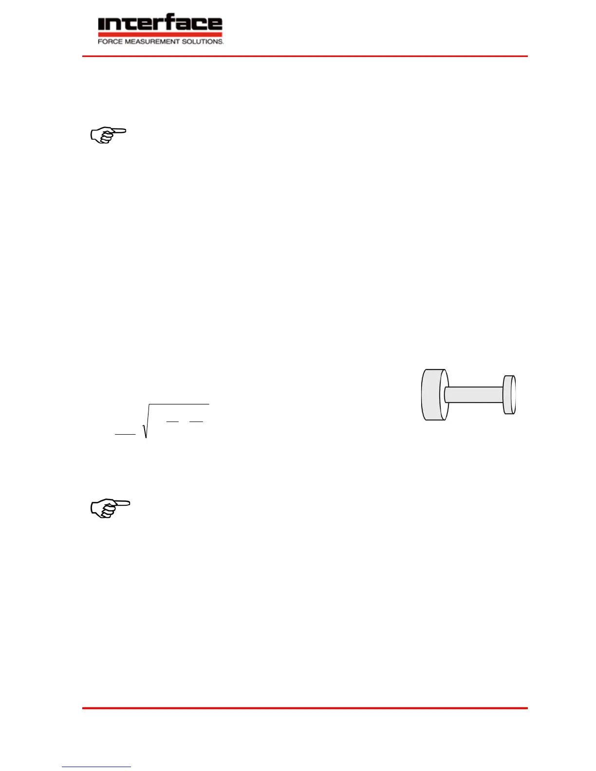
Natural Resonances
Estimate of the mechanical natural frequencies:
c
f
0
1
2
f
0
J
1
, J
2
c
= Natural Frequency in Hz
= Moment of Inertia in kg*m²
J
2
= Torsional Rigidity in Nm/rad
J
1
Further methods for the calculation of natural resonances are corresponding purchasable programs or books
(e.g. Holzer-Procedure, Dubbel, Taschenbuch für den Maschinenbau, Springer Verlag)
An operation of the device in natural resonance can lead to permanent damages.
Speed Limits
The maximum speed indicated in the data sheet may not be exceeded in any operating state...
Disturbance Variables
By disturbances, measured value falsifications can occur by
• Vibrations,
• Temperature gradients,
• Temperature changes,
• Arising disturbance variables during operation, e.g. imbalance,
• Electrical disturbances,
• Magnetic disturbances,
• EMC (electromagnetic disturbances),
Therefore avoid these disturbance variables by decoupling of vibrations, covers, etc.